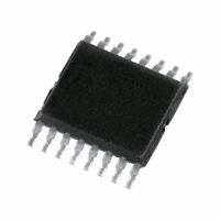
PCA9541APW/01,112 NXP Semiconductors, PCA9541APW/01,112 Datasheet - Page 13

PCA9541APW/01,112
Manufacturer Part Number
PCA9541APW/01,112
Description
IC I2C 2:1 SELECTOR 16-TSSOP
Manufacturer
NXP Semiconductors
Datasheet
1.PCA9541ABS03118.pdf
(41 pages)
Specifications of PCA9541APW/01,112
Package / Case
16-TSSOP
Applications
2-Channel I²C Multiplexer
Interface
I²C, SMBus
Voltage - Supply
2.3 V ~ 5.5 V
Mounting Type
Surface Mount
Maximum Operating Frequency
400 KHz
Maximum Operating Temperature
+ 85 C
Minimum Operating Temperature
- 40 C
Mounting Style
SMD/SMT
Supply Voltage (max)
5.5 V
Supply Voltage (min)
2.3 V
Lead Free Status / RoHS Status
Lead free / RoHS Compliant
Lead Free Status / RoHS Status
Lead free / RoHS Compliant, Lead free / RoHS Compliant
Other names
568-4938-5
935289365112
935289365112
NXP Semiconductors
Table 11.
PCA9541A_3
Product data sheet
Type version
PCA9541A/01 MST_0
PCA9541A/03 MST_0
Default Control Register values
Master
MST_1
MST_1
Table 12
master device wants to take control of the I
function of the current I
Control Register.
Current status of the I
NBUSON is one of the following:
‘I
‘I
Remark: Only the 4 LSBs of the Control Register are described in
those bits control the I
application and are not discussed in the table.
The read sequence is performed by the master as:
S - 111xxxx0 - 000x0001 - Sr - 111xxxx1 - DataRead - P
The write sequence is performed by the master as:
S - 111xxxx0 - 000x0001 - DataWritten - P
2
2
•
•
•
•
Bit 7
NTESTON TESTON
C-bus off’ means that upstream and downstream channels are not connected together.
C-bus on’ means that upstream and downstream channels are connected together.
The master reading its Control Register does not have control and the I
The master reading its Control Register does not have control and the I
The master reading its Control Register has control and the I
The master reading its Control Register has control and the I
0
0
0
0
describes which command needs to be written to the Control Register when a
Bit 6
0
0
0
0
2
2
C-bus is determined by the bits MYBUS, NMYBUS, BUSON and
2
C-bus control. The logic value for the 4 MSBs is specific to the
Rev. 03 — 16 July 2009
Bit 5
not used
C-bus control status performed after an initial reading of the
2-to-1 I
0
0
0
0
2
C-bus master selector with interrupt logic and reset
Bit 4
BUSINIT
0
0
0
0
2
C-bus. Byte written to the Control Register is a
Bit 3
NBUSON
0
1
0
0
Bit 2
BUSON
1
0
0
0
2
2
C-bus is off.
C-bus is on.
PCA9541A
Table 12
Bit 1
NMYBUS
© NXP B.V. 2009. All rights reserved.
0
1
0
1
2
2
since only
C-bus is off.
C-bus is on.
Bit 0
MYBUS
13 of 41
0
0
0
0


