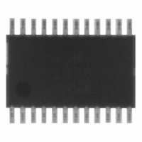
ADM1024ARUZ ON Semiconductor, ADM1024ARUZ Datasheet - Page 28

ADM1024ARUZ
Manufacturer Part Number
ADM1024ARUZ
Description
IC MONITOR SYS TEMP/VOLT 24TSSOP
Manufacturer
ON Semiconductor
Datasheet
1.ADM1024ARUZ.pdf
(29 pages)
Specifications of ADM1024ARUZ
Applications
PC's, PDA's
Interface
Serial
Voltage - Supply
2.8 V ~ 5.5 V
Package / Case
24-TSSOP
Mounting Type
Surface Mount
Temperature Sensor Function
Temp Sensor
Output Type
Digital
Package Type
TSSOP
Operating Temperature (min)
0C
Operating Temperature (max)
100C
Operating Temperature Classification
Commercial
Operating Supply Voltage (typ)
3.3V
Operating Supply Voltage (max)
5.5V
Full Temp Accuracy
+/- 2 C , +/- 3 C
Digital Output - Bus Interface
SMBus
Digital Output - Number Of Bits
10 bit
Supply Voltage (max)
12 V
Supply Voltage (min)
2.5 V
Maximum Operating Temperature
+ 100 C
Minimum Operating Temperature
0 C
Supply Current
1.4 mA
Lead Free Status / RoHS Status
Lead free / RoHS Compliant
Available stocks
Company
Part Number
Manufacturer
Quantity
Price
Part Number:
ADM1024ARUZ
Manufacturer:
ADI/亚德诺
Quantity:
20 000
1. An error that causes continuous interrupts to be generated may be masked in its respective mask register, until the error can be alleviated.
†For information on tape and reel specifications, including part orientation and tape sizes, please refer to our Tape and Reel Packaging
*The “Z’’ suffix indicates Pb−Free part.
Table 17. Register 4Ah, Configuration Register 2 (Power−On Default, [7:0] = 0x00h)
Table 18. Register 4Ch, Interrupt Status Register 1 Mirror (Power−On Default, [7:0] = 00h)
Table 19. Register 4Dh, Interrupt Status Register 2 Mirror (Power−On Default, [7:0] = 00h)
ORDERING INFORMATION
Specifications Brochure, BRD8011/D.
ADM1024ARUZ
ADM1024ARUZ−REEL
4, 5
Bit
Bit
Bit
0
1
2
3
6
7
0
1
2
3
4
5
6
7
0
1
2
3
4
5
6
7
Device Order Number
2.5 V/Ext. Temp2 Error
Control Register Write
Control Register Write
External Temp1 Error
Internal Temp Error
Ambient Temp Fan
Thermal INT Mask
Remote Temp Fan
THERM Interrupt
FAN1/A
FAN2/A
Interrupt Mode
Chassis Error
V
V
5.0 V Error
12 V Error
Reserved
V
Reserved
Reserved
IRQ3 EN
IRQ4 EN
CCP1
CCP2
Once Bit
Once Bit
D1 Fault
D2 Fault
THERM
CC
Name
Name
Name
IN1
IN2
Error
Error
Error
Error
Error
R/W once
R/W once
Read only
Read only
Read only
Read only
Read only
Read only
Read only
Read only
Read only
Read only
Read only
Read only
Read only
Read only
Read only
Read only
Read only
R/W
R/W
R/W
R/W
R/W
R/W
R/W
Temperature Range
0°C to +100°C
0°C to +100°C
Setting this bit masks the thermal interrupts for the INT output ONLY. The THERM
output will still be generated, regardless of the setting of this bit.
Writing a 1 to this bit will lock in the values set into the ambient temperature
automatic fan control register 13h. This register will not be able to be written again
until a reset is performed (either POR, Hard Reset, or Soft Reset).
Writing a 1 to this bit will lock in the values set into the remote temperature automatic
fan control register 14h. This register will not be able to be written again until a reset
is performed (either POR, Hard Reset, or Soft Reset).
If this bit is 0, the THERM output operates in default mode.
If this bit is 1, the THERM output operates in ACPI mode.
Reserved
Setting this bit to 1 enables Pin 21 as an active high interrupt input, provided Pins 20
to 24 have been configured as interrupts by setting Bit 7 of the Channel Mode
Register. Power−on default = 0.
Setting this bit to 1 enables Pin 20 as an active high interrupt input, provided Pins 20
to 24 have been configured as interrupts by setting Bit 7 of the Channel Mode
Register. Power−on default = 0.
A 1 indicates that a High or Low limit has been exceeded.
A 1 indicates that a High or Low limit has been exceeded.
A 1 indicates that a High or Low limit has been exceeded.
A 1 indicates that a High or Low limit has been exceeded.
A 1 indicates that a temperature interrupt has been set, or that a High or Low limit
has been exceeded.
A 1 indicates that a temperature interrupt has been set, or that a High or Low limit
has been exceeded.
A 1 indicates that a High or Low limit has been exceeded.
A 1 indicates that a High or Low limit has been exceeded.
A 1 indicates a High or Low limit has been exceeded.
A 1 indicates a High or Low limit has been exceeded.
Undefined.
Undefined.
A 1 indicates Chassis Intrusion has gone high.
Indicates that THERM pin has been pulled low by an external source.
Short or Open−Circuit Sensor Diode D1.
Short or Open−Circuit Sensor Diode D2.
http://onsemi.com
28
24−Lead TSSOP
24−Lead TSSOP
Package Type
Description
Description
Description
(Note 1)
2500 Tape & Reel
Shipping
62 Tube
†


