PX1011B-EL1/G,557 NXP Semiconductors, PX1011B-EL1/G,557 Datasheet - Page 25
PX1011B-EL1/G,557
Manufacturer Part Number
PX1011B-EL1/G,557
Description
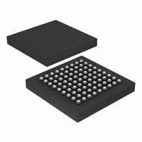
IC PCI-EXPRESS X1 PHY 81-LFBGA
Manufacturer
NXP Semiconductors
Datasheet
1.PX1011B-EL1G551.pdf
(30 pages)
Specifications of PX1011B-EL1/G,557
Package / Case
81-LFBGA
Applications
PCI Express MAX to PCI Express PHY
Interface
JTAG
Voltage - Supply
1.2 V
Mounting Type
Surface Mount
Product
PHY
Supply Voltage (max)
1.3 V, 2.7 V, 3.6 V
Supply Voltage (min)
1.15 V, 2.3 V, 3 V
Supply Current
0.028 A
Maximum Operating Temperature
+ 70 C
Minimum Operating Temperature
0 C
Mounting Style
SMD/SMT
Maximum Power Dissipation
300 mW
Number Of Channels
1
Lead Free Status / RoHS Status
Lead free / RoHS Compliant
Other names
935282113557
PX1011B-EL1/G
PX1011B-EL1/G
PX1011B-EL1/G
PX1011B-EL1/G
Available stocks
Company
Part Number
Manufacturer
Quantity
Price
Company:

Part Number:
PX1011B-EL1/G,557
Manufacturer:
NXP Semiconductors
Quantity:
10 000


NXP Semiconductors
13. Soldering of SMD packages
PX1011B_4
Product data sheet
13.1 Introduction to soldering
13.2 Wave and reflow soldering
13.3 Wave soldering
This text provides a very brief insight into a complex technology. A more in-depth account
of soldering ICs can be found in Application Note AN10365 “Surface mount reflow
soldering description” .
Soldering is one of the most common methods through which packages are attached to
Printed Circuit Boards (PCBs), to form electrical circuits. The soldered joint provides both
the mechanical and the electrical connection. There is no single soldering method that is
ideal for all IC packages. Wave soldering is often preferred when through-hole and
Surface Mount Devices (SMDs) are mixed on one printed wiring board; however, it is not
suitable for fine pitch SMDs. Reflow soldering is ideal for the small pitches and high
densities that come with increased miniaturization.
Wave soldering is a joining technology in which the joints are made by solder coming from
a standing wave of liquid solder. The wave soldering process is suitable for the following:
Not all SMDs can be wave soldered. Packages with solder balls, and some leadless
packages which have solder lands underneath the body, cannot be wave soldered. Also,
leaded SMDs with leads having a pitch smaller than ~0.6 mm cannot be wave soldered,
due to an increased probability of bridging.
The reflow soldering process involves applying solder paste to a board, followed by
component placement and exposure to a temperature profile. Leaded packages,
packages with solder balls, and leadless packages are all reflow solderable.
Key characteristics in both wave and reflow soldering are:
Key characteristics in wave soldering are:
•
•
•
•
•
•
•
•
•
•
Through-hole components
Leaded or leadless SMDs, which are glued to the surface of the printed circuit board
Board specifications, including the board finish, solder masks and vias
Package footprints, including solder thieves and orientation
The moisture sensitivity level of the packages
Package placement
Inspection and repair
Lead-free soldering versus SnPb soldering
Process issues, such as application of adhesive and flux, clinching of leads, board
transport, the solder wave parameters, and the time during which components are
exposed to the wave
Solder bath specifications, including temperature and impurities
Rev. 04 — 4 September 2009
PCI Express stand-alone X1 PHY
PX1011B
© NXP B.V. 2009. All rights reserved.
25 of 30
Related parts for PX1011B-EL1/G,557
Image
Part Number
Description
Manufacturer
Datasheet
Request
R

Part Number:
Description:
IC PCI-EXPRESS X1 PHY 81-LFBGA
Manufacturer:
NXP Semiconductors
Datasheet:
Part Number:
Description:
IC PCI-EXPRESS X1 PHY 81-LFBGA
Manufacturer:
NXP Semiconductors
Datasheet:
Part Number:
Description:
IC PCI-EXPRESS X1 PHY 81-LFBGA
Manufacturer:
NXP Semiconductors
Datasheet:

Part Number:
Description:
Telecom Line Management ICs PCI EXPRESS STAND ALONE X1 PHY
Manufacturer:
NXP Semiconductors
Part Number:
Description:
Telecom Line Management ICs PCI-EXPRESS X1 PHY STAND-ALONE
Manufacturer:
NXP Semiconductors
Part Number:
Description:
Peripheral Drivers & Components - PCIs PX1011B-EL1 LFBGA81 REEL13DP
Manufacturer:
NXP Semiconductors
Part Number:
Description:
Manufacturer:
NXP Semiconductors
Datasheet:
Part Number:
Description:
Pci Express Stand-alone X1 Phy Semiconductors
Manufacturer:
NXP Semiconductors
Datasheet:
Part Number:
Description:
Peripheral Drivers & Components - PCIs PCI EXPRESS STAND-ALONE X1 PHY
Manufacturer:
NXP Semiconductors
Part Number:
Description:
NXP Semiconductors designed the LPC2420/2460 microcontroller around a 16-bit/32-bitARM7TDMI-S CPU core with real-time debug interfaces that include both JTAG andembedded trace
Manufacturer:
NXP Semiconductors
Datasheet:

Part Number:
Description:
NXP Semiconductors designed the LPC2458 microcontroller around a 16-bit/32-bitARM7TDMI-S CPU core with real-time debug interfaces that include both JTAG andembedded trace
Manufacturer:
NXP Semiconductors
Datasheet:
Part Number:
Description:
NXP Semiconductors designed the LPC2468 microcontroller around a 16-bit/32-bitARM7TDMI-S CPU core with real-time debug interfaces that include both JTAG andembedded trace
Manufacturer:
NXP Semiconductors
Datasheet:
Part Number:
Description:
NXP Semiconductors designed the LPC2470 microcontroller, powered by theARM7TDMI-S core, to be a highly integrated microcontroller for a wide range ofapplications that require advanced communications and high quality graphic displays
Manufacturer:
NXP Semiconductors
Datasheet:
Part Number:
Description:
NXP Semiconductors designed the LPC2478 microcontroller, powered by theARM7TDMI-S core, to be a highly integrated microcontroller for a wide range ofapplications that require advanced communications and high quality graphic displays
Manufacturer:
NXP Semiconductors
Datasheet:
Part Number:
Description:
The Philips Semiconductors XA (eXtended Architecture) family of 16-bit single-chip microcontrollers is powerful enough to easily handle the requirements of high performance embedded applications, yet inexpensive enough to compete in the market for hi
Manufacturer:
NXP Semiconductors
Datasheet: