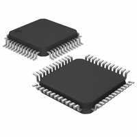
DS8007A-EAG+ Maxim Integrated Products, DS8007A-EAG+ Datasheet - Page 13

DS8007A-EAG+
Manufacturer Part Number
DS8007A-EAG+
Description
IC INTERFACE SMART CARD 48-LQFP
Manufacturer
Maxim Integrated Products
Datasheet
1.DS8007A-EAG.pdf
(41 pages)
Specifications of DS8007A-EAG+
Applications
Smart Card
Interface
Parallel
Voltage - Supply
2.7 V ~ 6 V
Package / Case
48-LQFP
Mounting Type
Surface Mount
Lead Free Status / RoHS Status
Lead free / RoHS Compliant
The following describes the major functional features of
the device. Use of this document requires the reader
have a basic understanding of ISO 7816 terminology.
The device interfaces to a host computer/processor
through a multiplexed or demultiplexed, parallel, 8-bit
data bus (D0–D7). The parallel bus interface monitors
the ALE signal and automatically detects whether a
multiplexed or nonmultiplexed external bus interface is
intended. The nonmultiplexed external bus interface is
the default configuration and is maintained so long as
Figure 6. Block Diagram
RSTOUT
PRESB
PRESA
DELAY
GNDB
GNDA
AGND
RSTB
CLKB
CPA1
CPA2
CPB1
CPB2
CLKA
V
RSTA
V
V
GND
I/OB
C4B
C8B
I/OA
C8A
C4A
V
CCB
DDA
V
CCA
DD
UP
______________________________________________________________________________________
Multiprotocol Dual Smart Card Interface
Parallel Bus Interface
Detailed Description
POWER-SUPPLY
SUPERVISOR
CONVERTER
DC-DC
INTERFACE
ANALOG
SEQUENCERS
CONTROL
DS8007A
no edge (activity) is detected on the ALE pin. Once a
rising edge is detected on the ALE pin, the DS8007A is
placed into the multiplexed mode of operation. Once in
the multiplexed mode of operation, a reset/power cycle
or the deassertion of CS forces the device to the non-
multiplexed mode. Connecting the ALE pin to V
ground forces the device into nonmultiplexed parallel
bus mode. Figure 7 shows that the bus recognition dic-
tates whether the external address lines (AD3–AD0)
can be used directly or whether the external data lines
(D7–D0) must be latched according to the ALE input
signal. In the multiplexed mode of operation, a new
address is latched irrespective of the state of CS.
COUNTER
TIMEOUT
UART
ISO
GENERATION
CLOCK
INTERFACE
DIGITAL
INT
D0
D4
XTAL1
XTAL2
CS
INTAUX
I/OAUX
AD0
AD1
AD2
AD3
ALE
RD
WR
D1
D2
D3
D5
D6
D7
DD
13
or


