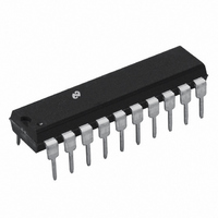
TP3420AN308 National Semiconductor, TP3420AN308 Datasheet - Page 12

TP3420AN308
Manufacturer Part Number
TP3420AN308
Description
IC INTERFACE DEVICE ISDN 20-DIP
Manufacturer
National Semiconductor
Datasheet
1.TP3420AV308-TRNOPB.pdf
(32 pages)
Specifications of TP3420AN308
Applications
*
Interface
*
Voltage - Supply
*
Package / Case
20-DIP (0.300", 7.62mm)
Mounting Type
Through Hole
Lead Free Status / RoHS Status
Contains lead / RoHS non-compliant
Other names
*TP3420AN308
Available stocks
Company
Part Number
Manufacturer
Quantity
Price
Company:
Part Number:
TP3420AN308
Manufacturer:
NS
Quantity:
6 231
Part Number:
TP3420AN308
Manufacturer:
N/A
Quantity:
20 000
www.national.com
Control Device State Reading
Disable the Device State Output on the NOCST (Note 6)
Control of Additional Interrupts
Enable the Slip and RMFE Interrupts
Disable the Slip and RMFE Interrupts (Note 6)
Control Polarity of B Channel Data
Invert B1 Channel Data
Invert B2 Channel Data
Normal B1, B2 Data (Note 6)
Pin Signal Selection
Redefine Pin Signals (See Table 1 )
Line Signal Detected Far-End
Activation Pending
Activation Indication
Error Indication
Deactivation Indication
End of D-ch Tx Message
Lost Contention for D-ch
Multiframe Receiver Buffer 1 (SC1/Q)
Multiframe Receiver Buffer 2 (SC2)
Multiframe Clock (5 ms or 30 ms)
Additional Interrupts after ENINT Command
Receive Multiframe Error
Phase Slip in Data Buffer for Bx Data
Phase Slip in Data Buffer for Br Data
Phase Slip for Both Bx and Br Data
NO Change Return Status
NOC Status after DISST Command (Note
9)
NOC Status after ENST Command
See Table 6 for Device State Decoding
Functional Description
Note 6: Indicates initial state following Power-on initialization.
Note 7: Slave-slave mode.
Note 8: DACCD is the power up default in TES mode and DACCE is the power up default in TEM mode.
Note 9: Indicates initial state following Power-on Initialization.
STATUS INDICATOR DESCRIPTIONS
LSD
AP
This interrupt indicates that the far-end of the line
is attempting to Activate the interface. May be
used as an alternative to the LSD pin to “wake-up”
a microprocessor.
If set, indicates that either INFO 1 frames have
been identified in an NT receiver, or INFO 2 or
INFO 4 frames have been identified in a TE re-
Function
Function
TABLE 4. Control Register Functions (Continued)
(Continued)
TABLE 5. Status Register Functions
LSD
AP
AI
EI
DI
EOM
CON
MFR1
MFR2
MFC
RMFE
SLIP TX
SLIP RX
SLIP TX/RX
NOC
NOCST
Mnemonic
DISST
ENINT
DISINT
INVB1
INVB2
NRMB12
PINDEF
Mnemonic
12
7
0
0
0
0
0
0
0
0
0
0
0
0
0
0
0
1
EOM
CON
S3
6
0
0
0
0
0
0
0
0
1
0
0
0
0
0
0
ceiver. Requires an AR control instruction to allow
Activation to be completed.
This interrupt occurs when the closing flag of a
D-channel message has been transmitted by a TE
on the S interface, indicating successful comple-
tion of a packet. The Interrupt associated with this
bit can be disabled via the Control Register if de-
sired.
This interrupt occurs when, during transmission of
7
1
1
1
1
1
1
1
S2
5
0
0
0
0
0
0
0
1
0
0
0
0
0
0
0
6
0
0
0
0
0
0
1
S1
Bit Number
4
0
0
0
0
0
0
0
1
1
0
0
0
0
0
0
5
0
0
0
0
0
0
1
Bit Number
M1
M1
4
1
1
1
1
1
1
0
3
0
0
1
1
1
0
0
0
0
1
1
1
0
0
3
0
0
0
1
1
1
0
M2
M2
2
0
0
1
1
1
1
1
1
1
0
0
0
0
0
x2
2
0
1
1
1
1
1
M3
M3
1
1
1
0
1
1
1
1
0
0
0
1
1
0
0
x1
1
1
0
0
0
1
1
M4
M4
0
0
1
0
0
1
0
1
0
1
1
0
1
0
0
x0
0
1
0
1
1
0
1


