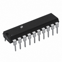
TP3420AN308 National Semiconductor, TP3420AN308 Datasheet - Page 14

TP3420AN308
Manufacturer Part Number
TP3420AN308
Description
IC INTERFACE DEVICE ISDN 20-DIP
Manufacturer
National Semiconductor
Datasheet
1.TP3420AV308-TRNOPB.pdf
(32 pages)
Specifications of TP3420AN308
Applications
*
Interface
*
Voltage - Supply
*
Package / Case
20-DIP (0.300", 7.62mm)
Mounting Type
Through Hole
Lead Free Status / RoHS Status
Contains lead / RoHS non-compliant
Other names
*TP3420AN308
Available stocks
Company
Part Number
Manufacturer
Quantity
Price
Company:
Part Number:
TP3420AN308
Manufacturer:
NS
Quantity:
6 231
Part Number:
TP3420AN308
Manufacturer:
N/A
Quantity:
20 000
www.national.com
Functional Description
DIGITAL INTERFACE FORMATS
DIF1)
DIF2)
DIF3)
DIF4)
BCLK FREQUENCY SETTINGS
BCLK1
BCLK2
BCLK3
BCLK4
B CHANNEL CONTROL
BDIR)
BEX )
B1E)
B1D)
B2E)
B2D)
INVB1,
INVB2
NRMB12
Note 10: When enabling a B channel in conjunction with the BEX Com-
mand, the channels are referenced at the Digital System Interface, not the
line interface e.g. to connect the B1 slot on the DSI with the B2 slot on the line
interface, use the BEX and B1E commands.
D CHANNEL ACCESS
DREQ1)
DREQ2)
These instructions select the format of the
Digital Interface timing, see Figure 3 and
Figure 4 .
These instructions change the frequency of a
selected Digital Interface Format. They
should only be used after the Digital
Interface Format has been selected.
However, if another DIF command is applied
after this command, it will override the BCLK
setting.
The default BCLK settings for the DIF
formats are as follows:
DIF1 BCLK1
DIF2 BCLK2
DIF3 BCLK3
DIF4 BCLK4
These commands provide for the exchange
of data between the B1 and B2 channels as
it passes through the device, (Note 10).
When either or both B channels are
disabled, binary 1s are transmitted on the
line in those B channel bit positions,
regardless of data at the Bx input, and the
Br output is TRI-STATE in those bit
positions.
These commands allow control over the
polarity of the data transmitted over the B1
and B2 channel. The default or the NRMB12
command sets the data to be operated in
normal mode. See section on operation over
restricted channels.
This is a request from Layer 2 device to the
TP3420A (in the TE modes) to attempt to
transmit a D channel message at the S
interface. Use DREQ1 to select the access
priority for a Class 1 message (Q.931
Signaling), or DREQ2 for a Class 2
message.
(Continued)
14
DACCE)
DACCD)
DCKE)
EIE
EID
EBITI,
EBIT0,
EBITNRM
LOOPBACK TEST MODES
Three classes of loopback mode are available on the SID,
selected by writing the appropriate Control instruction.
LBS
LBL1/2 These loopbacks turn each individual B channel
LBB1/2 These loopbacks at the Digital System Interface
CAL
EXTERNAL SELF-ACTIVATING LOOPBACK
A quick self-test of the device is possible by connecting to-
gether the line sides of the transmit and receive transform-
ers. NTA or NTF mode must be selected, and the device can
then be activated by the normal command sequence (Note
11).
Note 11: This test mode is not possible by direct connection of L
pins due to incompatible internal bias voltages.
This loopback at the system interface loops the two
B channels and the D channel from the B
the B
is activated, in which case it is transparent (i.e. the
channels are also transmitted to the line), or when
it is deactivated.
from the line receive input back to the line transmit
output. They may be set separately or together.
loop the B1 (LBB1) or the B2 (LBB2) channel data
from the B
is also sent to the line transmit output.
This command clears all loopbacks.
DACCD is the power-up default condition in
TES mode, and DACCE is the power-up
default condition in TEM mode. The D
channel Access algorithm can be enabled
(by DACCE) or disabled (DACCD) in both
TES mode or TEM mode. The D support a
passive bus network lines. The DENx pin
signal provides the flow control strobe
according to the access algorithm.
This command alters pin signals to provide
direct D-channel flow control with certain
HDLC devices. Pin 8 provides gated (DEN
DTCK, Pin 18 provides gated (DEN
and Pin 11 inputs TxD data.
See applications note to interface with
MC68302 for use of this command.
Enable EOM interrupt.
Disable EOM interrupt.
These commands allow control over the
D-Echo bit generated in the NT mode
device. The default state or the EBITNRM
command sets Echo bit to its normal
condition which is to reflect the received D
bit back out to the TEs as the Echo bit. The
EBIT0 command forces the Echo bit to be
set to “0” on every frame going back to the
TEs. The EBITI command forces the
transmitted Echo bit to be inverted from that
which is computed from incoming D bits.
r
output. It may be set either when the device
x
input to the B
r
output. The B
x
R
input data
x
) DRCK,
o
±
input to
and L
x
)
i
±


