EA-QSB-012 Embedded Artists, EA-QSB-012 Datasheet - Page 38
EA-QSB-012
Manufacturer Part Number
EA-QSB-012
Description
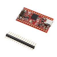
BOARD QUICK START LPC1343
Manufacturer
Embedded Artists
Specifications of EA-QSB-012
Lead Free Status / Rohs Status
Lead free / RoHS Compliant


NXP Semiconductors
Table 10.
LPC1311_13_42_43
Product data sheet
Peripheral
GPIO
IOCONFIG
I2C
ROM
SSP
UART
WDT
USB
USB
Power consumption for individual analog and digital blocks
9.4 Electrical pin characteristics
-
Typical supply current in mA
n/a
-
-
-
-
-
-
-
-
Fig 14. High-drive output: Typical HIGH-level output voltage V
12 MHz
0.21
0.00
0.03
0.04
0.11
0.20
0.01
-
1.84
V
(V)
OH
3.6
3.2
2.8
2.4
Conditions: V
output current I
2
0
0.80
48 MHz
0.02
0.12
0.15
0.41
0.76
0.05
3.91
4.19
All information provided in this document is subject to legal disclaimers.
DD
10
= 3.3 V; on pin PIO0_7.
Rev. 3 — 10 August 2010
72 MHz
1.17
0.02
0.17
0.22
0.60
1.11
0.08
-
5.71
OH
T = 85 °C
.
−40 °C
25 °C
20
GPIO pins configured as outputs and set to LOW. Direction
Notes
and pin state are maintained if the GPIO is disabled in the
SYSAHBCLKCFG register.
Main clock selected as clock source for the WDT.
Main clock selected as clock source for the USB. USB_DP
and USB_DM pulled LOW externally.
Dedicated USB PLL selected as cock source for the USB.
USB_DP and USB_DM pulled LOW externally.
30
…continued
32-bit ARM Cortex-M3 microcontroller
LPC1311/13/42/43
40
OH
versus HIGH-level
50
I
OH
002aae990
© NXP B.V. 2010. All rights reserved.
(mA)
60
38 of 62
Related parts for EA-QSB-012
Image
Part Number
Description
Manufacturer
Datasheet
Request
R

Part Number:
Description:
MCU, MPU & DSP Development Tools QUICKSTART PROTOTYPE BRD W/ LPC2129 CAN
Manufacturer:
Embedded Artists
Datasheet:

Part Number:
Description:
MCU, MPU & DSP Development Tools QUICKSTART PROTOTYPE BRD
Manufacturer:
Embedded Artists
Datasheet:

Part Number:
Description:
MCU, MPU & DSP Development Tools LPC2148 USB QUICKSTART BRD
Manufacturer:
Embedded Artists
Datasheet:

Part Number:
Description:
MCU, MPU & DSP Development Tools QUICKSTART PROTOTYPE BRD W/ LPC2106 RS232
Manufacturer:
Embedded Artists
Datasheet:
Part Number:
Description:
MCU, MPU & DSP Development Tools LPC2129 CAN QUICKSTART BRD
Manufacturer:
Embedded Artists
Datasheet:
Part Number:
Description:
MCU, MPU & DSP Development Tools QUICKSTART PROTOTYPE BRD W/ LPC2148
Manufacturer:
Embedded Artists
Datasheet:
Part Number:
Description:
MCU, MPU & DSP Development Tools LPC2106 RS232 QUICKSTART BRD
Manufacturer:
Embedded Artists
Datasheet:

Part Number:
Description:
Development Boards & Kits - ARM QUICK START BOARD LPC11U35
Manufacturer:
Embedded Artists
Datasheet:
Part Number:
Description:
KIT LPC3141 SODIMM 66X48 200POS
Manufacturer:
Embedded Artists
Datasheet:
Part Number:
Description:
KIT LPC3152 SODIMM 66X48 200POS
Manufacturer:
Embedded Artists
Datasheet:
Part Number:
Description:
BOARD OEM W/LPC2478 MCU
Manufacturer:
Embedded Artists
Datasheet:
Part Number:
Description:
KIT LPC3250 259 WITH QVGA
Manufacturer:
Embedded Artists
Datasheet: