ISL43840IRZ Intersil, ISL43840IRZ Datasheet
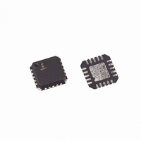
IC MUX/DEMUX DUAL 4X1 20QFN

ISL43840IRZ

Manufacturer Part Number
ISL43840IRZ
Description
IC MUX/DEMUX DUAL 4X1 20QFN
Manufacturer
Intersil
Type
Analog Multiplexerr
Datasheet

Specifications of ISL43840IRZ

Function
Multiplexer/Demultiplexer
Circuit
2 x 4:1
On-state Resistance
45 Ohm
Voltage Supply Source
Single, Dual Supply
Voltage - Supply, Single/dual (±)
±2 V ~ 6 V, 2 V ~ 12 V
Current - Supply
1µA
Operating Temperature
-40°C ~ 85°C
Mounting Type
Surface Mount
Package / Case
20-VFQFN Exposed Pad
Package
20QFN EP
Maximum On Resistance
155@3V Ohm
Maximum Propagation Delay Bus To Bus
60@±4.5V|50@10.8V|70@4.5V|120@3V ns
Maximum Low Level Output Current
30 mA
Multiplexer Architecture
4:1
Maximum Turn-off Time
50@3V ns
Maximum Turn-on Time
100@3V ns
Power Supply Type
Single|Dual
Lead Free Status / RoHS Status
Lead free / RoHS Compliant

Available stocks

Company
Part Number
Manufacturer
Quantity
Price
Part Number:
ISL43840IRZ
Manufacturer:
Intersil
Quantity:
525
Part Number:
ISL43840IRZ
Manufacturer:
INTERSIL
Quantity:
12 895
Low-Voltage, Single and Dual Supply,
Dual 4 to 1 Multiplexer Analog Switch with
Enable
The Intersil ISL43840 device is a precision, bidirectional,
analog switches configured as a a dual 4 channel multiplexer/
demultiplexer designed to operate from a single +2V to +12V
supply or from a
enable bar pins to simultaneously open all signal paths of
bank A and B.
ON resistance of 39Ω with a
+3.3V supply. Each switch can handle rail to rail analog
signals. The off-leakage current is only .01nA at +25°C or
2.5nA at +85°C
All digital inputs have 0.8V to 2.4V logic thresholds, ensuring
TTL/CMOS logic compatibility when using a single 3.3V or
+5V supply or dual
The ISL43840 is a dual 4 to 1 multiplexer device. Table 1
summarizes the performance of this part.
Related Literature
• Technical Brief TB363 “Guidelines for Handling and
• Application Note AN557 “Recommended Test Procedures
• Application Note AN520 “CMOS Analog Multiplexers and
• Application Note AN1034 “Analog Switch and Multiplexer
±5V R
±5V t
12V R
12V t
5V R
5V t
3.3V R
3.3V t
Package
Processing Moisture Sensitive Surface Mount Devices
(SMDs)”
for Analog Switches”
Switches; Specifications and Application Considerations.”
Applications”
ON
ON
ON
ON
ON
ON
ON
CONFIGURATION
ON
/ t
/ t
/ t
/ t
OFF
OFF
OFF
OFF
TABLE 1. FEATURES AT A GLANCE
.
±
2V to
±
5V supplies.
±
6V supply. The device has two
®
±
5V supply and 125Ω with a
1
39Ω
32ns/18ns
32Ω
23ns/15ns
65Ω
38ns/19ns
125Ω
70ns/32ns
20 Ld 4x4 QFN
Data Sheet
DUAL 4:1 MUX
1-888-INTERSIL or 1-888-468-3774
CAUTION: These devices are sensitive to electrostatic discharge; follow proper IC Handling Procedures.
Features
• Fully Specified at 3.3V, 5V,
• ON Resistance (R
• ON Resistance (R
• R
• Low Charge Injection, V
• Single Supply Operation. . . . . . . . . . . . . . . . . . . +2V to +12V
• Dual Supply Operation . . . . . . . . . . . . . . . . . . . . .
• Fast Switching Action (V
• Guaranteed Max Off-leakage . . . . . . . . . . . . . . . . . . . . 2.5nA
• Guaranteed Break-Before-Make
• TTL, CMOS Compatible
• Pb-Free Plus Anneal Available (RoHS Compliant)
Applications
• Communications Systems
• Test Equipment
• Audio and Video Signal Routing
• Various Circuits
Tolerances
- t
- t
- Radios
- Telecom Infrastructure
- ADSL, VDSL Modems
- Medical Ultrasound
- Magnetic Resonance Image
- CT and PET Scanners (MRI)
- ATE
- Electrocardiograph
- +3V/+5V DACs and ADCs
- Sample and Hold Circuits
- Operational Amplifier Gain Switching Networks
- High Frequency Analog Switching
- High Speed Multiplexing
- Integrator Reset Circuits
ON
ON
OFF
March 13, 2006
Matching Between Channels, V
. . . . . . . . . . . . . . . . . . . . . . . . . . . . . . . . . . . . 38ns
Copyright © Intersil Americas Inc. 2003, 2004, 2006. All Rights Reserved
. . . . . . . . . . . . . . . . . . . . . . . . . . . . . . . . . . . 19ns
|
Intersil (and design) is a registered trademark of Intersil Americas Inc.
ON
ON
) Max, V
) Max, V
S
S
=
= +5V)
±
±
5V, and 12V Supplies for 10%
5V . . . . . . . . . . . . . 1pC (Max)
S
S
=
= +3V . . . . . . . . . . . 155Ω
±
4.5V. . . . . . . . . . . 50Ω
S
=
ISL43840
±
5V . . . . . . . . <2Ω
FN6056.2
±
2V to
±
6V

Related parts for ISL43840IRZ

ISL43840IRZ Summary of contents

Page 1

... Intersil (and design registered trademark of Intersil Americas Inc. Copyright © Intersil Americas Inc. 2003, 2004, 2006. All Rights Reserved FN6056.2 ± ± ...

Page 2

... Ordering Information PART NUMBER SWITCH ON ISL43840IR NONE ISL43840IRZ NO0 (See Note) NO1 Add “-T” suffix for tape and reel. NO2 NOTE: Intersil Pb-free plus anneal products employ special Pb-free material sets; molding compounds/die attach materials and 100% NO3 matte tin plate termination finish, which are RoHS compliant and compatible with both SnPb and Pb-free soldering operations ...

Page 3

Absolute Maximum Ratings ...

Page 4

Electrical Specifications: ±5V SupplyTest Conditions: V PARAMETER = ±4.5V, V Address Transition Time TRANS ±5.5V, V Break-Before-Make Time BBM Charge Injection 1.0nF NO/NC OFF ...

Page 5

Electrical Specifications +12V Supply PARAMETER COM OFF Leakage Current 13.2V (Note 7) COM(OFF) COM ON Leakage Current 13.2V floating, (Note 7) COM(ON) DIGITAL INPUT CHARACTERISTICS Input Voltage High ENH ...

Page 6

Electrical Specifications: 5V Supply PARAMETER ANALOG SWITCH CHARACTERISTICS Analog Signal Range, V ANALOG ON Resistance 4.5V (See Figure 5) R Matching Between Channels 4.5V ∆ Flatness ...

Page 7

Electrical Specifications: 3.3V Supply PARAMETER ANALOG SWITCH CHARACTERISTICS Analog Signal Range, V ANALOG ON Resistance 3.0V (See Figure 5) R Matching Between Channels 3.0V ∆ Flatness ...

Page 8

Test Circuits and Waveforms 3V LOGIC 50% INPUT VNO0 90% SWITCH OUTPUT 0V t OFF Logic input waveform is inverted for switches that have the opposite logic sense. FIGURE 1A. ENABLE MEASUREMENT POINTS ON ...

Page 9

Test Circuits and Waveforms 3V LOGIC INPUT 0V SWITCH OUTPUT V OUT 0V t BBM FIGURE 3A. t MEASUREMENT POINTS BBM V+ SIGNAL GENERATOR NOX COMX ANALYZER GND R L FIGURE 4. OFF ISOLATION TEST CIRCUIT V+ SIGNAL GENERATOR NO ...

Page 10

Detailed Description The ISL43840 analog switch offers a precise switching capability from a bipolar ± ± single 2V to 12V supply with low on-resistance (39Ω) and high speed operation (t = 38ns 19ns) ...

Page 11

Leakage Considerations Reverse ESD protection diodes are internally connected between each analog-signal pin and both V+ and V-. One of these diodes conducts if any analog signal exceeds V+ or V-. Virtually all the analog leakage current comes from the ...

Page 12

Typical Performance Curves 500 V- = -5V 400 -40°C 300 25°C 200 25°C 100 85°C 0 -40°C 250 200 85°C 150 25°C 100 50 -40° (V) FIGURE 13. ENABLE ...

Page 13

Typical Performance Curves - 12V or = ±2V to ±5V - 50Ω L -30 -40 -50 -60 ISOLATION -70 -80 -90 -100 ALL HOSTILE CROSSTALK -110 1k 10k 100k 1M FREQUENCY (Hz) ...

Page 14

... Accordingly, the reader is cautioned to verify that data sheets are current before placing orders. Information furnished by Intersil is believed to be accurate and reliable. However, no responsibility is assumed by Intersil or its subsidiaries for its use; nor for any infringements of patents or other rights of third parties which may result from its use ...

Related keywords