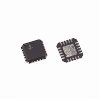
ISL43840IRZ Intersil, ISL43840IRZ Datasheet - Page 4

ISL43840IRZ
Manufacturer Part Number
ISL43840IRZ
Description
IC MUX/DEMUX DUAL 4X1 20QFN
Manufacturer
Intersil
Type
Analog Multiplexerr
Datasheet
1.ISL43840IRZ.pdf
(14 pages)
Specifications of ISL43840IRZ
Function
Multiplexer/Demultiplexer
Circuit
2 x 4:1
On-state Resistance
45 Ohm
Voltage Supply Source
Single, Dual Supply
Voltage - Supply, Single/dual (±)
±2 V ~ 6 V, 2 V ~ 12 V
Current - Supply
1µA
Operating Temperature
-40°C ~ 85°C
Mounting Type
Surface Mount
Package / Case
20-VFQFN Exposed Pad
Package
20QFN EP
Maximum On Resistance
155@3V Ohm
Maximum Propagation Delay Bus To Bus
60@±4.5V|50@10.8V|70@4.5V|120@3V ns
Maximum Low Level Output Current
30 mA
Multiplexer Architecture
4:1
Maximum Turn-off Time
50@3V ns
Maximum Turn-on Time
100@3V ns
Power Supply Type
Single|Dual
Lead Free Status / RoHS Status
Lead free / RoHS Compliant
Available stocks
Company
Part Number
Manufacturer
Quantity
Price
Company:
Part Number:
ISL43840IRZ
Manufacturer:
Intersil
Quantity:
525
Electrical Specifications:
NOTES:
Electrical Specifications +12V Supply
Address Transition Time, t
Break-Before-Make Time, t
Charge Injection, Q
NO/NC OFF Capacitance, C
COM OFF Capacitance, C
COM ON Capacitance, C
OFF Isolation
Crosstalk, (Note 8)
All Hostile Crosstalk, (Note 8)
POWER SUPPLY CHARACTERISTICS
Power Supply Range
Positive Supply Current, I+
Negative Supply Current, I-
ANALOG SWITCH CHARACTERISTICS
Analog Signal Range, V
ON Resistance, R
R
∆R
R
NO or NC OFF Leakage Current,
I
3. V
4. The algebraic convention, whereby the most negative value is a minimum and the most positive a maximum, is used in this data sheet.
5. ∆R
6. Flatness is defined as the difference between maximum and minimum value of on-resistance over the specified analog signal range.
7. Leakage parameter is 100% tested at high temp, and guaranteed by correlation at 25°C.
8. Between any two switches.
NO(OFF)
ON
ON
ON
IN
Matching Between Channels,
Flatness, R
ON
= logic voltage to configure the device in a given state.
or I
= R
PARAMETER
PARAMETER
NC(OFF)
ON
FLAT(ON)
(MAX) - R
ON
ANALOG
COM(ON)
TRANS
OFF
BBM
ON
OFF
(MIN).
4
±5V SupplyTest Conditions: V
V
V
V
V
C
f = 1MHz, V
f = 1MHz, V
f = 1MHz, V
R
(See Figures 4 and 6)
V
V+ = 10.8V, I
V+ = 10.8V, I
V+ = 10.8V, I
V+ = 13.2V, V
(Note 7)
S
IN
S
IN
S
L
L
= ±4.5V, V
= ±5.5V, V
= 1.0nF, V
= 50Ω, C
= ±5.5V, V
= 0 to 3, (See Figure 1)
= 0 to 3V, (See Figure 3)
NO
NO
NO
L
COM
COM
COM
COM
G
NO
NO
ENH
= 15pF, f = 100kHz, V
Unless Otherwise Specified (Continued)
= V
= V
= V
= 0V, R
TEST CONDITIONS
TEST CONDITIONS
Test Conditions: V+ = +10.8V to +13.2V, GND = 0V, V
Unless Otherwise Specified
= ±3V, R
= 3V, R
= 1.0mA, V
, V
= 1.0mA, V
= 1.0mA, V
= 1V, 12V, V
COM
COM
COM
ADD
G
= 0V, (See Figure 7)
= 0V, (See Figure 7)
= 0V, (See Figure 7)
L
= 0Ω, (See Figure 2
= 0V or V+, Switch On or Off
SUPPLY
L
= 300Ω, C
ISL43840
= 300Ω, C
NO
NO
NO
NO
= 9V, (Note 5)
= 3V, 6V, 9V, (Note 6)
= 9V, (See Figure 5)
= 12V, 1V,
= ±4.5V to ±5.5V, GND = 0V, V
NO
L
L
= 35pF,
= 1V
= 35pF,
RMS
,
TEMP
TEMP
(°C)
(°C)
Full
Full
Full
Full
Full
Full
Full
Full
Full
Full
25
25
25
25
25
25
25
25
25
25
25
25
25
25
INH
(NOTE 4)
(NOTE 4)
MIN
MIN
-0.1
-2.5
±2
= 2.4V, V
-1
-1
-1
-1
2
0
-
-
-
-
-
-
-
-
-
-
-
-
-
-
-
INH
= 4V, V
INL
0.002
≤110
TYP
-105
TYP
0.3
0.1
0.1
1.2
43
12
18
92
37
7
3
5
-
-
-
-
-
-
-
-
INL
= 0.8V (Note 3),
= 0.8V (Note 3),
(NOTE 4)
(NOTE 4)
MAX
MAX
0.1
2.5
V+
60
70
±6
45
55
1
1
1
1
1
2
2
7
7
-
-
-
-
-
-
-
March 13, 2006
UNITS
UNITS
FN6056.2
pC
dB
dB
µA
µA
µA
µA
nA
nA
pF
pF
pF
dB
ns
ns
ns
V
V
Ω
Ω
Ω
Ω
Ω
Ω


