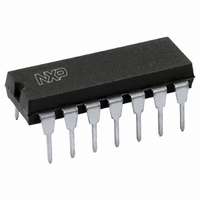
74HCT4016N,112 NXP Semiconductors, 74HCT4016N,112 Datasheet - Page 8

74HCT4016N,112
Manufacturer Part Number
74HCT4016N,112
Description
IC SWITCH QUAD SPST 14DIP
Manufacturer
NXP Semiconductors
Series
74HCTr
Datasheets
1.74HCT4046ADB112.pdf
(19 pages)
2.74HCT4046ADB112.pdf
(23 pages)
3.74HCT4016N112.pdf
(14 pages)
Specifications of 74HCT4016N,112
Package / Case
14-DIP (0.300", 7.62mm)
Function
Switch
Circuit
4 x SPST - NO
On-state Resistance
80 Ohm
Voltage Supply Source
Single Supply
Voltage - Supply, Single/dual (±)
4.5 V ~ 5.5 V
Current - Supply
2µA
Mounting Type
Through Hole
Switch Configuration
SPST
On Resistance (max)
320 Ohm @ 4.5 V
On Time (max)
35 ns @ 4.5 V
Off Time (max)
35 ns @ 4.5 V
Supply Voltage (max)
5.5 V
Supply Voltage (min)
4.5 V
Maximum Power Dissipation
750 mW
Maximum Operating Temperature
+ 125 C
Mounting Style
Through Hole
Minimum Operating Temperature
- 40 C
Lead Free Status / RoHS Status
Lead free / RoHS Compliant
Lead Free Status / RoHS Status
Lead free / RoHS Compliant, Lead free / RoHS Compliant
Other names
568-2845-5
933668980112
933668980112
Philips Semiconductors
DC CHARACTERISTICS FOR 74HC
Voltages are referenced to GND (ground = 0 V)
AC CHARACTERISTICS FOR 74HC
GND = 0 V; t
December 1990
SYMBOL PARAMETER
V
V
I
SYMBOL PARAMETER
t
t
t
CC
PHL
PZH
PHZ
I
I
I
IH
IL
Quad bilateral switches
I
S
S
/ t
/ t
/ t
PLH
PZL
PLZ
HIGH level input
voltage
LOW level input
voltage
input leakage
current
analog switch
OFF-state current
per channel
analog switch
ON-state current
quiescent supply
current
propagation
delay
turn “ON” time
turn “OFF” time
r
= t
V
E
E
is
n
n
f
to V
to V
to V
= 6 ns; C
os
os
os
L
= 50 pF
min.
1.5
3.15
4.2
6.3
min.
17
6
5
4
52
19
15
11
47
17
14
13
typ.
25
1.2
2.4
3.2
4.3
0.8
2.1
2.8
4.3
typ. max. min. max. min.
25
60
12
10
8
190
38
32
28
145
29
25
22
max. min. max.
0.50
1.35
1.80
2.70
0.1
0.2
0.1
0.1
2.0
4.0
T
amb
74HC
T
amb
40 to 85
74HC
1.5
3.15
4.2
6.3
( C)
40 to 85
( C)
75
15
13
10
240
48
41
35
180
36
31
28
8
0.50
1.35
1.80
2.70
1.0
2.0
1.0
1.0
20.0
40.0
min.
1.5
3.15
4.2
6.3
40 to 125
40 to 125
90
18
15
12
235
57
48
42
220
44
38
33
max.
0.50
1.35
1.80
2.70
1.0
2.0
1.0
1.0
40.0
80.0
max.
UNIT
ns
ns
ns
UNIT
V
V
A
A
A
A
V
2.0
4.5
6.0
9.0
2.0
4.5
6.0
9.0
2.0
4.5
6.0
9.0
(V)
CC
2.0
4.5
6.0
9.0
2.0
4.5
6.0
9.0
6.0
10.0
10.0 V
10.0 V
6.0
10.0
V
(V)
74HC/HCT4016
CC
TEST CONDITIONS
TEST CONDITIONS
OTHER
R
(see Fig.16)
R
(see Figs 17 and 18)
R
(see Figs 17 and 18)
L
L
L
V
or
GND
or
V
or
V
V
or
GND
Product specification
= ; C
= 1 k ; C
= 1 k ; C
CC
IH
IL
IH
IL
CC
V
I
V
(see Fig.7)
V
(see Fig.8)
V
V
V
L
V
V
CC
CC
is
CC
CC
= 50 pF
S
S
OTHER
L
L
= GND or
; V
or GND
= 50 pF
= 50 pF
=
=
GND
GND
os
=


