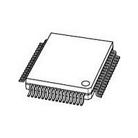
PCF8578H NXP Semiconductors, PCF8578H Datasheet - Page 21

PCF8578H
Manufacturer Part Number
PCF8578H
Description
Manufacturer
NXP Semiconductors
Datasheet
1.PCF8578H.pdf
(48 pages)
Specifications of PCF8578H
Operating Supply Voltage (typ)
3.3/5V
Operating Temperature (min)
-40C
Operating Temperature (max)
85C
Operating Temperature Classification
Industrial
Package Type
LQFP
Pin Count
64
Mounting
Surface Mount
Power Dissipation
400mW
Operating Supply Voltage (min)
2.5V
Operating Supply Voltage (max)
6V
Lead Free Status / Rohs Status
Compliant
Available stocks
Company
Part Number
Manufacturer
Quantity
Price
Part Number:
PCF8578H
Manufacturer:
PHILIPS/飞利浦
Quantity:
20 000
Company:
Part Number:
PCF8578H/1,118
Manufacturer:
NXP Semiconductors
Quantity:
10 000
Company:
Part Number:
PCF8578H/1,157
Manufacturer:
NXP Semiconductors
Quantity:
10 000
Part Number:
PCF8578HT
Manufacturer:
NXP/恩智浦
Quantity:
20 000
Company:
Part Number:
PCF8578HT/1
Manufacturer:
NXP
Quantity:
12 000
Part Number:
PCF8578HT/1
Manufacturer:
NXP/恩智浦
Quantity:
20 000
Company:
Part Number:
PCF8578HT/1,518
Manufacturer:
NXP Semiconductors
Quantity:
10 000
Part Number:
PCF8578HT/1,518
Manufacturer:
NXP/恩智浦
Quantity:
20 000
Company:
Part Number:
PCF8578HT1
Manufacturer:
NXP
Quantity:
6 520
Philips Semiconductors
8.1
The command decoder identifies command bytes that
arrive on the I
command is the continuation bit C (see Fig.14). When this
bit is set, it indicates that the next byte to be transferred will
also be a command. If the bit is reset, it indicates the
conclusion of the command transfer. Further bytes will be
regarded as display data. Commands are transferred in
WRITE mode only.
The five commands available to the PCF8578 are defined
in Tables 5 and 6.
Table 5 Summary of commands
Note
1. C = command continuation bit. D = may be a logic 1 or 0.
2003 Apr 14
SET MODE
SET START BANK
DEVICE SELECT
RAM ACCESS
LOAD X-ADDRESS
LCD row/column driver for
dot matrix graphic displays
COMMAND
Command decoder
2
C-bus. The most-significant bit of a
C
C
C
C
C
1
1
1
1
0
D
0
1
1
1
OPCODE
D
D
1
0
1
D
D
D
D
1
(1)
D
D
D
D
1
21
D
D
D
D
D
D
D
D
D
D
C = 0; last command.
C = 1; commands continue.
Fig.14 General information of command byte.
multiplex rate, display status, system type
defines bank at top of LCD
defines device subaddress
graphic mode, bank select (D D D D
allowed; see SET START BANK opcode)
0 to 39
MSB
C
REST OF OPCODE
DESCRIPTION
Product specification
MSA833
PCF8578
LSB
12 is not


