HR1S-AC5121 IDEC, HR1S-AC5121 Datasheet
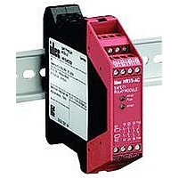
47T1434

HR1S-AC5121

Manufacturer Part Number
HR1S-AC5121
Description
47T1434
Manufacturer
IDEC
Datasheet

Specifications of HR1S-AC5121

Coil Voltage Vac Nom
24V
Coil Voltage Vdc Nom
24V
Relay Mounting
DIN Rail
External Height
99mm
External Width
22.5mm
External Depth
114mm
Safety Control Relay HR1S-AC
Part Numbers
Specifications
Use a 4A fuse (Type gL) for power fuse protection.
Use a 4A (Type gL) or a 6A fast blow fuse for output fuse protection.
Part Numbers
HR1S-AC5121
HR1S-AC5121P
Operating Temperature
Degree of Protection
Rated Power Voltage
Power Consumption
Overcurrent Protection
Control Circuit Voltage
Performance Level (PL)
Safety Category
Safety Integrity Level (SIL)
Response Time
Input Synchronization Time
Overvoltage Category
Pollution Degree
Rated Insulation Voltage
Operation Frequency
Rated Current
Wire Size
Weight
1NC or 2NC safety input type, such as E-Stops or Interlock Switches
EN ISO 13849-1 PLe, Safety Cat 3 compliant, and EN 62061 SIL 3
Fault diagnosis function with dual safety circuits.
Internal relay operations can be moni tored with LED Indicator.
Finger-safe protection
22.5mm wide, 35mm DIN rail mounting
UL listed, CSA certified, TÜV NORD approved
Instantaneous
(Stop Cat 0)
Auxiliary Contact
Safety
Circuit
Transistor Circuit
Minimum
Applicable Load
AC-15
DC-13
Terminal Style
Integrated Terminal Block
Removable Terminal Block
–10 to 55°C (no freezing)
Terminal: IP20, Housing: IP40
24V AC (–20 to +10%) 50/60 Hz
24V DC (±20%)
AC: 2.2 VA (24V AC) maximum
DC: 1.2W (24V DC) maximum
Electronic
24V
e (EN ISO 13849-1)
3 (EN 954-1)
3 (EN 62061)
100ms maximum
Unlimited
III
2
300V
3NO
1NO (transistor, PNP)
C300: Ue= 240VAC, Ie=0.75A
Ue=24VDC, Ie=2A
24V/20mA
17V/10mA (initial value)
1200 operations/h maximum
Safety circuit output total: 10.5A maximum
HR1S-AC5121: 1 × 2.5mm
HR1S-AC5121P: 1 × 2.5mm
160g
2
, 2 × 0.75mm
2
, 2 × 1.5mm
2
2
maximum
maximum
22.5
Dimensions (mm)
LED Indicator
22.5
A1/A2 Fuse:
Turns on when power circuit is normal.
Turns off when power is interrupted or the electronic fuse blows.
K1: Turns on when K1 relay operates.
K2: Turns on when K2 relay operates.
A1/A2
Fuse
K1/K2
A1/A2
Fuse
K1/K2
The HR1S-AC5121P terminal block can be
removed and installed as shown, allow-
ing for easy installation and replacement
of modules.
114
A1
14
A1
A2
114
13
24
14
Y43
23
Y1
24
Y44
33
Y2
34
Terminal Arrangement
A1
14
A1
A2
24
13
14 24
Y43 Y44
Y1
23
Y2
33
34

Related parts for HR1S-AC5121

HR1S-AC5121 Summary of contents

Page 1

... Turns on when power circuit is normal. Turns off when power is interrupted or the electronic fuse blows. • K1: Turns on when K1 relay operates. • K2: Turns on when K2 relay operates. The HR1S-AC5121P terminal block can be removed and installed as shown, allow- ing for easy installation and replacement of modules × 0.75mm maximum ...

Page 2

... Safety Category 3 Example Circuit (using an emergency stop switch with 2NC contacts) F1 Fuse (+) ( HR1S-AC LOGIC + A1/A2 K1/K2 T – (–) Safety Category 1 Example Circuit (using an emergency stop switch with 1NC contact) L1 (+) F1 Fuses: 4A (gL) ( HR1S-AC + LOGIC A1/A2 K1/K2 T – (–) Output Contact Electrical Life 100 AC15: 230V DC13: 24V ESC +24V DC ...

Page 3

... HR1S-AC Safety Relay Module Operation Chart When Using a Start Switch Power ON Emergency Stop Switch A1 (NC1) Emergency Stop Switch A2 Start Switch Operated (NC2) OFF Feedback Circuit with Start Switch (Y1-Y2) Output 13-14 (NO Contact) Output 23-24 (NO Contact) Output 33-34 (NO Contact) Transistor Output Y43-Y44 (NO Contact) ...

Related keywords