HR1S-ATE5110 IDEC, HR1S-ATE5110 Datasheet

47T1437

HR1S-ATE5110

Manufacturer Part Number
HR1S-ATE5110
Description
47T1437
Manufacturer
IDEC
Datasheet
Safety Control Relay HR1S-ATE
Part Numbers
Specifications
Note: Safety output contact
Applicable Standards
for Use
Performance Level (PL)
Safety Category
Safety Integrity Level (SIL)
Stop Category
Operating Temperature
Relative Humidity
Impulse Withstand Voltage
Shock Resistance
Vibration Resistance
Degree of Protection
Rated Voltage
Power Consumption
Overcurrent Protection
Minimal Applicable Load
Response Time
Overvoltage Category
Pollution Degree
Rated Insulation Voltage
Mechanical Durability
Electrical Life
Rated Current
Wire Size
Weight (approx.)
Part Numbers
HR1S-ATE5110
HR1S-ATE5110P
Use a 4A fuse (Type gG) for power protection. Use a 6A fuse (Type gG) for safety output
protection. Use a 4A fuse (Type gG) for time-delay output and auxiliary output protection.
EN ISO 13849-1 Performance Level e, Safety Category 4
compliant, and EN 62061 Safety Integrity Level 3.
Integrated and removable teminal styles available.
Compact design: 45 mm in width.
Time delay outputs: 3NO
Auxiliary outputs enable monitoring of power, safety inputs, and a time
delay output
Environmentally friendly, RoHs directive compliant.
UL Listed, CSA certified, TÜV NORD approved.
Instantaneous (Stop Cat 0)
Time-delay (Stop Cat 1)
Monitor Contacts
Safety
Circuit
Time-
delay
Circuit
Auxiliary Circuit
Time-delay output contact
HR1S-ATE5110
HR1S-ATE5110P
AC15
DC13
AC15
DC13
Preset Time
EN 60204-1: 2007, EN 60947-1: 2007
EN 60947-5-1:2004, EN 61000-6-2: 2005
EN 61000-6-4: 2007, EN 62061: 2005
EN ISO 13849-1: 2008, EN ISO 13849-2: 2008
EN 60204-1: 2006
EN ISO 13850: 2008
e (EN ISO 13849-1)
4 (EN ISO 13849-1)
3 (EN 62061)
0, 1 (EN 60204-1) (Note)
–10 to +55ºC (no freezing)
30 to 85% RH (no condensation)
4 kV (IEC 60947-5-1)
150 m/s2, 11m sec, 3 shocks in each 3 axes
10 to 60 Hz, amplitude 0.35 mm
60 to 150 Hz, acceleration 50 m/s2
Terminal: IP20 Enclosure: IP40
24V AC –20% +10%
24V DC –20% +20%
24V AC: 8 VA max. 24V DC: 4W max.
Built-in, electronic
17V DC / 10 mA (initial value)
ON to OFF: 20 ms max. (instantaneous output)
III
2
300V AC
2NO
3NO
4NO (PNP)
C300 (230V AC / Ie=0.75A)
24V DC / Ie=1A
C300 (230V AC/ Ie=0.75A)
24V DC / Ie=1A
0, 0.5, 1, 2, 4, 6, 8, 10, 15, 20, 25, 30 sec.
24V DC / 20 mA (PNP)
10,000,000 operations
See Output Contact Electrical Life graph (last page)
Total output: 8A max. 1 output 4A max.
Single wire: 0.2 to 2.5 mm2 max. (24~14 AWG)
Multiple wires: 0.14 to 0.75 mm2 max.
Single wire: 0.2 to 2.5 mm2 max.(24~14 AWG)
Multiple wires: 0.2 to 1.5 mm2 max.
280g
Terminal Style
Integrated Terminal Block
Removable Terminal Block
Stop category 0
Stop category 1
Dimensions (mm)
HR1S-ATE5110P Removable Terminal Type
LED Indicator
HR1S-ATE5110 Integrated Terminal Type
Input A
S12
A1/A2
Fuse
Input B
S22
Stop 1
114
114
Input B S22:
Stop1:
A1/A2 Fuse:
Input A S12:
Turns on when power circuit is normal.
Turns on when S11–S12 is closed.
Turns on when S21–S22 is closed.
Turns on when the time-delay output
circuits 57-58, 67-68, and 77-78 are closed.
45
45

Related parts for HR1S-ATE5110

HR1S-ATE5110 Summary of contents

Page 1

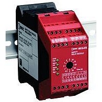
... Stop category 1 • Use a 4A fuse (Type gG) for power protection. Use a 6A fuse (Type gG) for safety output protection. Use a 4A fuse (Type gG) for time-delay output and auxiliary output protection. Dimensions (mm) HR1S-ATE5110 Integrated Terminal Type 114 HR1S-ATE5110P Removable Terminal Type 114 LED Indicator A1/A2 Fuse: Turns on when power circuit is normal ...

Page 2

... HR1S-ATE Wiring Diagram Safety Category 4 (3) Example Circuit (using an emergency stop switch) L1 (+) F1 (max. 4A S21 S11 B1 S12 S22 HR1S-ATE Time ( S33 Y1 ESC S2 N (–) 1. When monitoring the start switch, starts when switched off (default setting/recommended) 2. When monitoring the start switch, starts when switched on 3 ...

Page 3

... Residual Risk (EN ISO/ISO12100-1) The wiring diagrams on previous page have been tested under actual oper- ating conditions. The HR1S-ATE safety relay module can be used in a safety circuit by connecting to safety equipment compliant to applicable standards. Consider residual risk in the following circumstances: a) When it is necessary to modify the recommended circuit and if added/ modified components are not properly integrated into the control circuit ...

Related keywords