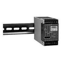
ES-FL-2A BANNER ENGINEERING, ES-FL-2A Datasheet - Page 6

ES-FL-2A
Manufacturer Part Number
ES-FL-2A
Description
20H6269
Manufacturer
BANNER ENGINEERING
Datasheet
1.ES-FL-2A.pdf
(8 pages)
Specifications of ES-FL-2A
Coil Voltage Vac Nom
24V
Coil Voltage Vdc Nom
24V
Contact Current Max
4A
Contact Voltage Ac Nom
250V
Contact Voltage Dc Nom
250V
Contact Configuration
DPDT-NC
No. Of Poles
2
E-Stop Safety Relay
The hookup diagram (Figure 2) shows a generic connection of the ES-FL-2A safety relay’s two redundant output circuits to master
stop control elements MSC1 and MSC2. A master stop control element is defined as an electrically-powered device, external to the
ES-FL-2A safety relay, which stops the machinery being controlled by immediate removal of electrical power to the machine and
(when necessary) by applying braking to dangerous motion (reference ANSI B11.19, section 5.2: “Stop Control”). This stopping
action is accomplished by removing power to the actuator of either master stop control element.
To satisfy the requirements of Safety Category 4 of prEN 954-1, the master stop control elements must be safety relays which offer
a normally-closed forced-guided monitor contact. One normally-closed monitor contact from each master stop control element is
wired in a series connection together with the normally-open RESET switch (see Figure 2). In operation, if one of the switching
contacts of either master stop control element fails in the shorted condition, the associated monitor contact will remain open.
Therefore, it will not be possible to reset the ES-FL-2A safety relay.
The reset circuit switch can be any mechanical switch such as a normally-open momentary switch, a two-position key switch, etc.
The reset switch must be capable of reliably switching 12 to 18V dc at 40 to 100 milliamps. As shown in Figure 2, and discussed,
above, the reset switch must be wired in series with a normally-closed monitor contact of each of the two master stop control
elements. This series circuit connects between terminals S33 and S34 of the safety relay.
The reset switch must be located outside of the area of dangerous motion, and must be positioned so that any area of
dangerous motion may be observed by the switch operator during the reset operation.
IMPORTANT NOTE: Any access to dangerous machine motion must be guarded using safety interlocks and/or point-of-
operation presence sensing devices which prevent hazardous machine motion when interrupted. Presence sensing devices,
such as safety mats, must be used in any space between machine guards and any danger point which is large enough to allow
a person to stand undetected by presence sensing devices.
The action of the auxiliary monitor contact, K3, inversely “follows” the action of the output relays, K1 and K2 when power is
applied to the ES-FL-2A safety relay. The contact of K3 is open when the output contacts of K1 and K2 are closed, and vice versa.
The K3 auxiliary monitor contact is a light-duty contact to be used only for control functions that are NOT safety-related. A
typical use is to communicate the status of the safety relay output to a programmable logic controller (PLC). The switching
capacity of the K3 auxiliary monitor contact is 125V ac or V dc maximum at 500 mA maximum (resistive load). Connection to the
auxiliary monitor contact is made at terminals 41 and 42 (see Figure 2).
Checkout procedure:
1) Remove power from the machine control elements.
2) Activate the emergency stop switch (open its contacts).
page
SECTION 4.2 – Connection to the Machine to be Controlled
SECTION 4.3 – Connection of Reset Switch
SECTION 4.4 – Connection to the Auxiliary Monitor Contact
SECTION 5 – Initial Checkout Procedure
6
CAUTION
machine to be controlled. Dangerous voltages may be present along the ES-FL-2A wiring barriers whenever
power to the machine control elements is “on”. Exercise extreme caution whenever machine control power
is or may be present. Always disconnect power to the machine control elements before opening the
enclosure housing the ES-FL-2A.
Before performing the initial checkout procedure, make certain all power is disconnected from the


