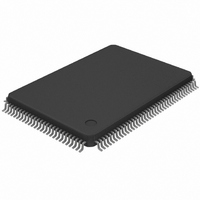
MAX4356ECD+T Maxim Integrated Products, MAX4356ECD+T Datasheet - Page 36

MAX4356ECD+T
Manufacturer Part Number
MAX4356ECD+T
Description
IC VIDEO CROSSPOINT SWIT 128TQFP
Manufacturer
Maxim Integrated Products
Datasheet
1.MAX4356ECD.pdf
(41 pages)
Specifications of MAX4356ECD+T
Function
Video Crosspoint Switch
Circuit
1 x 16:16
Voltage Supply Source
Single, Dual Supply
Voltage - Supply, Single/dual (±)
5V, ± 3 V ~ 5 V
Operating Temperature
-40°C ~ 85°C
Mounting Type
Surface Mount
Package / Case
128-TQFP, 128-VQFP
Lead Free Status / RoHS Status
Lead free / RoHS Compliant
16 x 16 Nonblocking Video Crosspoint Switch
with On-Screen Display Insertion and I/O Buffers
Figure 6. 128 x 32 Nonblocking Matrix Using 16 x 16 Crosspoint Devices
crosspoint devices to reduce the number of outputs
that need to be wired together (see Figure 7).
In Figure 7, the additional devices are placed in a sec-
ond bank to multiplex the signals. This reduces the
number of wired-OR connections. Another solution is to
put a small resistor in series with the output before the
capacitive load to limit excessive ringing and oscilla-
tions. Figure 8 shows the graph of the Optimal Isolation
Resistor vs. Capacitive Load. A lowpass filter is created
from the series resistor and parasitic capacitance to
ground. A single R-C do not affect the performance at
video frequencies, but in a very large system there may
be many R-Cs cascaded in series. The cumulative
effect is a slight rolling off of the high frequencies caus-
ing a "softening" of the picture. There are two solutions
to achieve higher performance. One way is to design
the PC board traces associated with the outputs such
that they exhibit some inductance. By routing the traces
in a repeating "S" configuration, the traces that are
nearest each other will exhibit a mutual inductance
increasing the total inductance. This series inductance
causes the amplitude response to increase or peak at
higher frequencies, offsetting the rolloff from the para-
sitic capacitance. Another solution is to add a small-
value inductor to the output.
The MAX4356 facilitates the insertion of on-screen
graphics and characters by using the built-in fast 2:1
multiplexer associated with each of the 16 outputs
(Functional Diagram). This mux switches in 40ns, much
36
______________________________________________________________________________________
IN (16–31)
IN (32–47)
IN (48–63)
IN (0–15)
On-Screen Display Insertion
16
IN
16
IN
16
IN
16
IN
MAX4356
MAX4356
MAX4356
MAX4356
OUT
OUT
OUT
OUT
OUTPUTS (0–15)
16
16
16
16
16
IN
16
IN
16
IN
16
IN
MAX4356
MAX4356
MAX4356
MAX4356
OUTPUTS (16–32)
OUT
OUT
OUT
OUT
16
16
16
16
IN (112–127)
IN (96–111)
IN (64–79)
IN (80–95)
Figure 7. 64 x 16 Nonblocking Matrix with Reduced Capacitive
Loading
IN (16–31)
IN (32–47)
IN (48–63)
less than the width of a single pixel. Access to this fast
mux is through 16 dedicated OSDFILL analog inputs
and 16 dedicated OSDKEY input controls. OSD timing
is externally controlled and applied to the OSDKEY
inputs (Figure 1). Pulling OSDKEY i low switches the
signal on the OSDFILL
the OSDKEY signal is logic high, the signal at IN_ is
switched to the output. This switching action is repeat-
ed on a pixel-by-pixel basis for each scan line. In this
way any synchronized video signal, including arbitrary
graphics, can be inserted on the screen (Figure 9).
IN (0–15)
16
IN
16
IN
16
IN
16
IN
MAX4356
MAX4356
MAX4356
MAX4356
16
IN
16
IN
16
IN
16
IN
MAX4356
MAX4356
MAX4356
MAX4356
OUT
OUT
OUT
OUT
16
16
16
16
OUT
OUT
OUT
OUT
16
16
16
16
i
input to the OUT
16
IN
16
IN
16
IN
16
IN
16
IN
16
IN
MAX4356
MAX4356
MAX4356
MAX4356
MAX4356
MAX4356
OUT
OUT
OUT
OUT
16
16
16
16
OUT
OUT
16
16
i
output. When
OUTPUTS (0–15)


