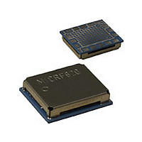
MICRF620 Micrel Inc, MICRF620 Datasheet - Page 19

MICRF620
Manufacturer Part Number
MICRF620
Description
Manufacturer
Micrel Inc
Datasheet
1.MICRF620.pdf
(21 pages)
Specifications of MICRF620
Operating Temperature (min)
-20C
Operating Temperature Classification
Commercial
Modulation Type
FSK
Lead Free Status / Rohs Status
Not Compliant
Assembling the MICRF620
Recommended Reflow Temperature Profile
When the MICRF620 module is being automatically
assembled to a PCB, care must be taken not to expose
the module for temperature above the maximum specified.
Figure 13 shows the recommended reflow temperature
profile.
Shock/Vibration during Reflow
The module has several components inside which are
assembled in a reflow process. These components may
reflow again when the module is assembled onto a PCB. It
is therefore important that the module is not subjected to
any mechanical shock or vibration during this process.
Handassembling the MICRF620
It is recommended to use solder paste also during hand
assembling of the module. Because of the module ground
pad on the bottom side, the module will be assembled
most efficient if the heat is being subjected to the bottom
side of the PCB. The heat will be transferred trough the
PCB due the ground vias under the module (see Layout
Considerations). In addition, it is recommended to use a
solder tip on the signal and power pads, to make sure the
solder points are properly melted.
Micrel, Inc.
July 2006
Figure 13. Recommended Reflow Temperature Reflow
19
Layout
Recommended Land Pattern
Figure 14 shows a recommended land pattern that
facilitates both automatic and hand assembling.
Figure 14. Recommended Land Pattern (TOP VIEW)
MICRF620/MICRF620Z
M9999-120205


