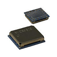
MICRF620 Micrel Inc, MICRF620 Datasheet - Page 20

MICRF620
Manufacturer Part Number
MICRF620
Description
Manufacturer
Micrel Inc
Datasheet
1.MICRF620.pdf
(21 pages)
Specifications of MICRF620
Operating Temperature (min)
-20C
Operating Temperature Classification
Commercial
Modulation Type
FSK
Lead Free Status / Rohs Status
Not Compliant
Layout Considerations
Except for the antenna input/output signal, only digital and
low frequency signals need to interface with the module.
There is therefore no need of years of RF expertise to do a
successful layout, as long as the following few points are
being followed:
Micrel, Inc.
July 2006
•
•
•
•
Proper ground is needed. If the PCB is 2-layer, the
bottom layer should be kept only for ground. Avoid
signal traces that split the ground plane. For a 4-
layer PCB, it is recommended to keep the second
layer only for ground.
A ground via should be placed close to all the
ground pins. The bottom ground pad should be
penetrated with 4-16 ground vias.
The antenna has an impedance of ~50 ohm. The
antenna trace should be kept to 50 ohm to avoid
signal reflection and loss of performance. Any
transmission line calculator can be used to find the
needed trace width given a board build up. Ex: A
trace width of 44 mil (1.12 mm) gives 50
impedance on a FR4 board (dielectric cons=4.4)
with copper thickness of 35µm and height (layer 1-
layer 2 spacing) of 0.61 mm.
RF circuitry is sensitive to voltage supply and
therefore caution should be taken when choosing
power circuitry. To achieve the best performance,
20
•
low noise LDO’s with high PSSR should be
chosen. What is present on the voltage supply will
be directly modulated to the RF spectrum causing
degradation and regulatory issues. To make sure
you have the right selection, please contact local
sales for the latest Micrel offerings in power
management and guidance. To avoid “pickup”
from other circuitry on the VDD lines, it is
recommended to route the VDD in a star
configuration with decoupling at each circuitry and
at the common connection point (see above
layout). If there are noisy circuitry in the design, it
is strongly recommended to use a separate power
supply and/or place low value resistors (10ohms),
inductors in series with the power supply line into
these circuitry.
Digital
should/must be at a safe distance from RF
circuitry or RF VDD as this might/will cause
degradation of sensitivity and create spurious
emissions. Example of such circuitry is LCD
display, charge pumps, RS232, clock / data bus
etc.
high
speed
logic
MICRF620/MICRF620Z
or
noisy
M9999-120205
circuitry


