DS2153Q-A7+T&R Maxim Integrated Products, DS2153Q-A7+T&R Datasheet - Page 16
DS2153Q-A7+T&R
Manufacturer Part Number
DS2153Q-A7+T&R
Description
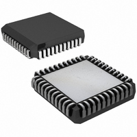
IC TXRX E1 1-CHIP 5V 44-PLCC
Manufacturer
Maxim Integrated Products
Datasheet
1.DS2153Q-A7TR.pdf
(60 pages)
Specifications of DS2153Q-A7+T&R
Function
Single-Chip Transceiver
Interface
E1
Number Of Circuits
1
Voltage - Supply
4.75 V ~ 5.25 V
Current - Supply
65mA
Operating Temperature
0°C ~ 70°C
Mounting Type
Surface Mount
Package / Case
*
Lead Free Status / RoHS Status
Lead free / RoHS Compliant
Power (watts)
-


CCR3: COMMON CONTROL REGISTER 3 (Address = 1B Hex)
(MSB)
TESE
SYMBOL
TSCLKM
TCBFS
LIRST
TIRFS
TESE
ESR
—
—
TCBFS
POSITION
CCR3.7
CCR3.6
CCR3.5
CCR3.4
CCR3.3
CCR3.2
CCR3.1
CCR3.0
TIRFS
NAME AND DESCRIPTION
Transmit Elastic Store Enable.
0 = elastic store is disabled
1 = elastic store is enabled
Transmit Channel Blocking Registers (TCBR) Function
Select.
0 = TCBRs define the operation of the TCHBLK output pin
1 = TCBRs define which signaling bits are to be inserted
Transmit Idle Registers (TIR) Function Select.
0 = TIRs define in which channels to insert idle code
1 = TIRs define in which channels to insert data from RSER
Elastic Stores Reset. Setting this bit from a 1 to a 0 will force
the elastic stores to a known depth. Should be toggled after
SYSCLK has been applied and is stable. Must be set and cleared
again for a subsequent reset. Do not leave this bit set high.
Line Interface Reset. Setting this bit from a 0 to a 1 will initiate
an internal reset that affects the slicer, AGC, clock recovery state
machine, and jitter attenuator. Normally this bit is only toggled
on power-up. Must be cleared and set again for a subsequent
reset.
Not Assigned. Should be set to 0 when written.
Transmit Backplane Clock Select. Must be set like RCR2.2.
0 = 1.544MHz
1 = 2.048MHz
Not Assigned. Should be set to 0 when written.
ESR
16 of 60
LIRST
—
TSCLKM
(LSB)
—
Related parts for DS2153Q-A7+T&R
Image
Part Number
Description
Manufacturer
Datasheet
Request
R

Part Number:
Description:
Manufacturer:
Maxim Integrated Products
Datasheet:

Part Number:
Description:
IC TXRX E1 1-CHIP 5V 44-PLCC
Manufacturer:
Maxim Integrated Products
Part Number:
Description:
IC TXRX E1 1-CHIP 5V 44-PLCC
Manufacturer:
Maxim Integrated Products
Part Number:
Description:
MAX7528KCWPMaxim Integrated Products [CMOS Dual 8-Bit Buffered Multiplying DACs]
Manufacturer:
Maxim Integrated Products
Datasheet:
Part Number:
Description:
Single +5V, fully integrated, 1.25Gbps laser diode driver.
Manufacturer:
Maxim Integrated Products
Datasheet:
Part Number:
Description:
Single +5V, fully integrated, 155Mbps laser diode driver.
Manufacturer:
Maxim Integrated Products
Datasheet:
Part Number:
Description:
VRD11/VRD10, K8 Rev F 2/3/4-Phase PWM Controllers with Integrated Dual MOSFET Drivers
Manufacturer:
Maxim Integrated Products
Datasheet:
Part Number:
Description:
Highly Integrated Level 2 SMBus Battery Chargers
Manufacturer:
Maxim Integrated Products
Datasheet:
Part Number:
Description:
Current Monitor and Accumulator with Integrated Sense Resistor; ; Temperature Range: -40°C to +85°C
Manufacturer:
Maxim Integrated Products
Part Number:
Description:
TSSOP 14/A°/RS-485 Transceivers with Integrated 100O/120O Termination Resis
Manufacturer:
Maxim Integrated Products
Part Number:
Description:
TSSOP 14/A°/RS-485 Transceivers with Integrated 100O/120O Termination Resis
Manufacturer:
Maxim Integrated Products
Part Number:
Description:
QFN 16/A°/AC-DC and DC-DC Peak-Current-Mode Converters with Integrated Step
Manufacturer:
Maxim Integrated Products
Part Number:
Description:
TDFN/A/65V, 1A, 600KHZ, SYNCHRONOUS STEP-DOWN REGULATOR WITH INTEGRATED SWI
Manufacturer:
Maxim Integrated Products
Part Number:
Description:
Integrated Temperature Controller f
Manufacturer:
Maxim Integrated Products
Part Number:
Description:
SOT23-6/I°/45MHz to 650MHz, Integrated IF VCOs with Differential Output
Manufacturer:
Maxim Integrated Products