DS2153Q-A7+T&R Maxim Integrated Products, DS2153Q-A7+T&R Datasheet - Page 41
DS2153Q-A7+T&R
Manufacturer Part Number
DS2153Q-A7+T&R
Description
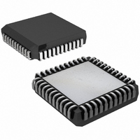
IC TXRX E1 1-CHIP 5V 44-PLCC
Manufacturer
Maxim Integrated Products
Datasheet
1.DS2153Q-A7TR.pdf
(60 pages)
Specifications of DS2153Q-A7+T&R
Function
Single-Chip Transceiver
Interface
E1
Number Of Circuits
1
Voltage - Supply
4.75 V ~ 5.25 V
Current - Supply
65mA
Operating Temperature
0°C ~ 70°C
Mounting Type
Surface Mount
Package / Case
*
Lead Free Status / RoHS Status
Lead free / RoHS Compliant
Power (watts)
-


13.2 Transmit Waveshaping and Line Driving
The DS2153Q uses a set of laser-trimmed delay lines along with a precision digital-to-analog converter
(DAC) to create the waveforms that are transmitted onto the E1 line. The waveforms created by the
DS2153Q meet the ITU specifications. See
generated by properly programming the L0 to L2 bits in the Line Interface Control Register (LICR). The
DS2153Q can set up in a number of various configurations depending on the application. See
and
Table 13-2. LBO Select in LICR
N.M. = not meaningful
Due to the nature of the design of the transmitter in the DS2153Q, very little jitter (less than 0.005UI
broadband from 10Hz to 100kHz) is added to the jitter present on TCLK. Also, the waveforms that they
create are independent of the duty cycle of TCLK. The transmitter in the DS2153Q couples to the E1
transmit shielded twisted pair or coax via a 1:1.15 or 1:1.36 step-up transformer as shown in
For the devices to create the proper waveforms, the transformer used must meet the specifications listed
in
Table 13-3. Transformer Specifications
Turns Ratio
Primary Inductance
Leakage Inductance
Intertwining Capacitance
DC Resistance
L2
0
0
0
0
1
1
1
Table
Figure
SPECIFICATION
L1
0
0
1
1
0
1
0
13-3.
1-1.
L0
0
1
0
1
0
0
0
75Ω normal
120Ω normal
75Ω normal with protection
resistors
120Ω normal with protection
resistors
75Ω with high return loss
75Ω with high return loss
120Ω with high return loss
APPLICATION
1:1 (receive) and 1:1.15 or 1:1.36 (transmit) ±5%
600µH minimum
1.0µH maximum
60pF maximum
1.2Ω maximum
RECOMMENDED VALUE
Figure
41 of 60
13-3. The user will select which waveform is to be
TRANSFORMER
1:1.15 step-up
1:1.15 step-up
1:1.15 step-up
1:1.15 step-up
1:1.15 step-up
1:1.36 step-up
1:1.36 step-up
RETURN LOSS
N.M.
N.M.
N.M.
N.M.
(dB)
21
21
21
Figure
Table 13-2
Rt (Ω)
8.2
8.2
27
18
27
0
0
13-1.
P-P
Related parts for DS2153Q-A7+T&R
Image
Part Number
Description
Manufacturer
Datasheet
Request
R

Part Number:
Description:
Manufacturer:
Maxim Integrated Products
Datasheet:

Part Number:
Description:
IC TXRX E1 1-CHIP 5V 44-PLCC
Manufacturer:
Maxim Integrated Products
Part Number:
Description:
IC TXRX E1 1-CHIP 5V 44-PLCC
Manufacturer:
Maxim Integrated Products
Part Number:
Description:
MAX7528KCWPMaxim Integrated Products [CMOS Dual 8-Bit Buffered Multiplying DACs]
Manufacturer:
Maxim Integrated Products
Datasheet:
Part Number:
Description:
Single +5V, fully integrated, 1.25Gbps laser diode driver.
Manufacturer:
Maxim Integrated Products
Datasheet:
Part Number:
Description:
Single +5V, fully integrated, 155Mbps laser diode driver.
Manufacturer:
Maxim Integrated Products
Datasheet:
Part Number:
Description:
VRD11/VRD10, K8 Rev F 2/3/4-Phase PWM Controllers with Integrated Dual MOSFET Drivers
Manufacturer:
Maxim Integrated Products
Datasheet:
Part Number:
Description:
Highly Integrated Level 2 SMBus Battery Chargers
Manufacturer:
Maxim Integrated Products
Datasheet:
Part Number:
Description:
Current Monitor and Accumulator with Integrated Sense Resistor; ; Temperature Range: -40°C to +85°C
Manufacturer:
Maxim Integrated Products
Part Number:
Description:
TSSOP 14/A°/RS-485 Transceivers with Integrated 100O/120O Termination Resis
Manufacturer:
Maxim Integrated Products
Part Number:
Description:
TSSOP 14/A°/RS-485 Transceivers with Integrated 100O/120O Termination Resis
Manufacturer:
Maxim Integrated Products
Part Number:
Description:
QFN 16/A°/AC-DC and DC-DC Peak-Current-Mode Converters with Integrated Step
Manufacturer:
Maxim Integrated Products
Part Number:
Description:
TDFN/A/65V, 1A, 600KHZ, SYNCHRONOUS STEP-DOWN REGULATOR WITH INTEGRATED SWI
Manufacturer:
Maxim Integrated Products
Part Number:
Description:
Integrated Temperature Controller f
Manufacturer:
Maxim Integrated Products
Part Number:
Description:
SOT23-6/I°/45MHz to 650MHz, Integrated IF VCOs with Differential Output
Manufacturer:
Maxim Integrated Products