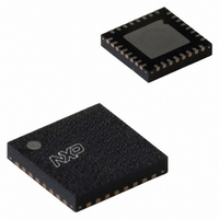
SC16IS762IBS,151 NXP Semiconductors, SC16IS762IBS,151 Datasheet - Page 39

SC16IS762IBS,151
Manufacturer Part Number
SC16IS762IBS,151
Description
IC UART DUAL I2C/SPI 32-HVQFN
Manufacturer
NXP Semiconductors
Type
IrDA or RS- 232 or RS- 485r
Datasheet
1.SC16IS752IBS151.pdf
(59 pages)
Specifications of SC16IS762IBS,151
Number Of Channels
2, DUART
Package / Case
32-VFQFN Exposed Pad
Features
Low Current
Fifo's
64 Byte
Protocol
RS232, RS485
Voltage - Supply
2.5V, 3.3V
With Auto Flow Control
Yes
With False Start Bit Detection
Yes
With Modem Control
Yes
Mounting Type
Surface Mount
Data Rate
5 Mbps
Supply Voltage (max)
3.6 V
Supply Voltage (min)
2.3 V
Supply Current
6 mA
Maximum Operating Temperature
+ 95 C
Minimum Operating Temperature
- 40 C
Mounting Style
SMD/SMT
Operating Supply Voltage
2.5 V or 3.3 V
Lead Free Status / RoHS Status
Lead free / RoHS Compliant
For Use With
568-4000 - DEMO BOARD SPI/I2C TO DUAL UART568-3510 - DEMO BOARD SPI/I2C TO UART
Lead Free Status / Rohs Status
Lead free / RoHS Compliant
Other names
568-2240
935279293151
SC16IS762IBS-S
935279293151
SC16IS762IBS-S
NXP Semiconductors
SC16IS752_SC16IS762_7
Product data sheet
10.3 Addressing
10.4 Use of subaddresses
Before any data is transmitted or received, the master must send the address of the
receiver via the SDA line. The first byte after the START condition carries the address of
the slave device and the read/write bit.
address can be selected by using A1 and A0 pins. For example, if these 2 pins are
connected to V
master communicates with it through this address.
Table 32.
[1]
When a master communicates with the SC16IS752/SC16IS762 it must send a
subaddress in the byte following the slave address byte. This subaddress is the internal
address of the word the master wants to access for a single byte transfer, or the beginning
of a sequence of locations for a multi-byte transfer. A subaddress is an 8-bit byte. Unlike
the device address, it does not contain a direction (R/W) bit, and like any byte transferred
on the bus it must be followed by an acknowledge.
A register write cycle is shown in
byte with the direction bit set to ‘write’, a subaddress byte, a number of data bytes, and a
STOP signal. The subaddress indicates which register the master wants to access, and
the data bytes which follow will be written one after the other to the subaddress location.
Table 33
SPI interfaces. Bit 0 is not used, bits 2:1 select the channel, bits 6:3 select one of the
UART internal registers. Bit 7 is not used with the I
SPI interface to indicate a read or a write operation.
A1
V
V
V
V
V
V
V
V
SCL
SCL
SCL
SCL
SDA
SDA
SDA
SDA
DD
DD
DD
DD
SS
SS
SS
SS
X = logic 0 for write cycle; X = logic 1 for read cycle.
and
SC16IS752/SC16IS762 address map
A0
V
V
SCL
SDA
V
V
SCL
SDA
V
V
SCL
SDA
V
V
SCL
SDA
DD
SS
DD
SS
DD
SS
DD
SS
Table 34
DD
, then the SC16IS752/SC16IS762’s address is set to 0x90, and the
show the bits’ presentation at the subaddress byte for I
Dual UART with I
SC16IS752/SC16IS762 I
0x90 (1001 000X)
0x92 (1001 001X)
0x98 (1001 100X)
0x9A (1001 101X)
0xA0 (1010 000X)
0xA2 (1010 001X)
0xA8 (1010 100X)
0xAA (1010 101X)
0x94 (1001 010X)
0x96 (1001 011X)
0x9C (1001 110X)
0x9E (1001 111X)
0xA4 (1010 010X)
0xA6 (1010 011X)
0xAC (1010 110X)
0xAE (1010 111X)
Rev. 07 — 19 May 2008
Figure
Table 32
18. The START is followed by a slave address
2
SC16IS752/SC16IS762
C-bus/SPI interface, 64-byte FIFOs, IrDA SIR
2
C address (hex)
shows how the SC16IS752/SC16IS762’s
2
C-bus interface, but it is used by the
[1]
© NXP B.V. 2008. All rights reserved.
2
C-bus and
39 of 59


