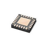
MAX3107ETG+ Maxim Integrated Products, MAX3107ETG+ Datasheet - Page 22

MAX3107ETG+
Manufacturer Part Number
MAX3107ETG+
Description
IC UART SPI/I2C 128 FIFO 24TQFN
Manufacturer
Maxim Integrated Products
Datasheet
1.MAX3107EAG.pdf
(52 pages)
Specifications of MAX3107ETG+
Features
Internal Oscillators
Number Of Channels
4, QUART
Fifo's
128 Byte
Protocol
RS232, RS485
Voltage - Supply
2.35 V ~ 3.6 V
With Auto Flow Control
Yes
With Irda Encoder/decoder
Yes
With False Start Bit Detection
Yes
Mounting Type
Surface Mount
Package / Case
24-TQFN Exposed Pad
Data Rate
24 Mbps
Supply Voltage (max)
3.3 V
Supply Voltage (min)
2.35 V
Supply Current
0.64 mA
Maximum Operating Temperature
+ 85 C
Minimum Operating Temperature
- 40 C
Mounting Style
SMD/SMT
No. Of Channels
1
Uart Features
128-Word Transmit / Receive FIFO, Half-Duplex Echo Suppression, Shutdown And Autosleep Modes
Supply Voltage Range
2.35V To 3.6V
Rohs Compliant
Yes
Lead Free Status / RoHS Status
Lead free / RoHS Compliant
SPI/I
and Internal Oscillator
If auto transmitter control (FlowCtrl[5:4]) is enabled, the
receiver compares all received words with the XOFF and
XON characters. If a XOFF is received, the MAX3107
halts its transmitter from sending further data. The
receiver is not affected and continues reception. Upon
receiving an XON, the transmitter restarts sending data.
The received XON and XOFF characters are filtered out
and are not put into the receive FIFO, as they do not have
significance to the higher layer protocol.
Turn the transmitter off (MODE1[1]) before enabling
transmitter control.
If auto receiver overflow control (FlowCtrl[7:6]) is enabled,
the MAX3107 automatically sends XOFF and XON con-
trol characters to the far-end UART to avoid receiver
overflow. XOFF1/XOFF2 are sent when the receive FIFO
fill level reaches the HALT value set in the FlowLvl regis-
ter. When the host controller reads data from the Receive
FIFO to a level equal to the RESUME level programmed
into the FlowLvl register, XON1/XON2 are automatically
sent to the far-end station to signal it to resume data
transmission.
If dual-character (XON1 and XON2/XOFF1 and XOFF2)
flow control is selected, XON1/XOFF1 are transmitted
before XON2/XOFF2.
Receive and transmit FIFO fill-dependent interrupts are
generated if FIFO trigger levels are defined. When the
number of words in the FIFOs reach or exceed a trigger
level, as programmed in FIFOTrgLvl, an ISR[3] or ISR[4]
interrupt is generated. There is no relationship between
the trigger levels and the HALT or RESUME levels.
The FIFO trigger level can, for example, be used for a
block data transfer, since it gives the host an indication
when a given block size of data is available for readout
in the teceive FIFO or available for transfer to the transmit
FIFO.
The sleep and shutdown modes reduce power con-
sumption during periods of inactivity. In both sleep and
shutdown modes, the UART disables specific functional
blocks to reduce power consumption.
In forced sleep mode, all UART-related on-chip clock-
ing is stopped. The following are inactive: the crystal
oscillator, the internal oscillator, the PLL, the predivider,
the receiver, and the transmitter. The SPI/I
22
_____________________________________________________________________________________
2
C UART with 128-Word FIFOs
Low-Power Standby Modes
FIFO Interrupt Triggering
Receiver Overflow Control
Transmitter Control
Forced Sleep Mode
2
C interface
and the registers remain active. Thus, the host control-
ler can access the resisters. To enter sleep mode, set
MODE1[5] to 1. To wake up, set MODE1[5] to 0.
The MAX3107 can be configured to operate in autosleep
mode by setting MODE1[6] to 1. In autosleep mode, the
MAX3107 automatically enters sleep mode when all the
following conditions are met:
• Both FIFOs are empty.
• There are no pending IRQ interrupts.
• There is no activity on any input pins for a period equal
The MAX3107 exits autosleep mode as soon as activity
is detected on any of the GPIO_, RX, or CTS inputs.
To manually wake up the MAX3107, set MODE1[6] to 0.
After wake-up is initiated, the internal clock starts up and
a period of time is needed for clock stabilization. The
STSInt[5]: ClockReady bit indicates when the clocks are
stable. If an external clock source is used, the STSInt[5]
bit does not indicate clock stability.
Shutdown mode is the lowest power consumption mode.
In shutdown mode, all the MAX3107 circuitry is off. This
includes the I
and clocking circuitry. The LDO is kept on. To enter shut-
down mode, connect RST to DGND.
When the RST input is toggled high, the MAX3107 exits
shutdown mode. When the MAX3107 sets IRQ to logic-
high, the chip initialization is completed. The MAX3107
needs to be reprogrammed following a shutdown.
IRQ has two functions. During normal operation
(MODE1[7] is 1), IRQ operates as a hardware interrupt
output, whereby the IRQ is active when an interrupt
is pending. An IRQ interrupt is only produced during
normal operation, if at least one of the IRQEn interrupt
enable bits are enabled.
During power-up or following a reset, IRQ has a differ-
ent function. It is held low until the MAX3107 is ready for
programming following an initialization delay. Once IRQ
goes high, the MAX3107 is ready to be programmed.
The MODE1[7]: IRQSel bit should then be set in order to
enable normal IRQ interrupt operation.
In polled mode, the RevID register can be polled to
check whether the MAX3107 is ready for operation. If
the controller gets a valid response from RevID, then the
MAX3107 is ready for operation.
to 65,536 UART characters lengths.
2
C/SPI interface, the registers, the FIFOs,
Power-Up and IRQ
Autosleep Mode
Shutdown Mode


