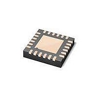
MAX3107ETG+ Maxim Integrated Products, MAX3107ETG+ Datasheet - Page 49

MAX3107ETG+
Manufacturer Part Number
MAX3107ETG+
Description
IC UART SPI/I2C 128 FIFO 24TQFN
Manufacturer
Maxim Integrated Products
Datasheet
1.MAX3107EAG.pdf
(52 pages)
Specifications of MAX3107ETG+
Features
Internal Oscillators
Number Of Channels
4, QUART
Fifo's
128 Byte
Protocol
RS232, RS485
Voltage - Supply
2.35 V ~ 3.6 V
With Auto Flow Control
Yes
With Irda Encoder/decoder
Yes
With False Start Bit Detection
Yes
Mounting Type
Surface Mount
Package / Case
24-TQFN Exposed Pad
Data Rate
24 Mbps
Supply Voltage (max)
3.3 V
Supply Voltage (min)
2.35 V
Supply Current
0.64 mA
Maximum Operating Temperature
+ 85 C
Minimum Operating Temperature
- 40 C
Mounting Style
SMD/SMT
No. Of Channels
1
Uart Features
128-Word Transmit / Receive FIFO, Half-Duplex Echo Suppression, Shutdown And Autosleep Modes
Supply Voltage Range
2.35V To 3.6V
Rohs Compliant
Yes
Lead Free Status / RoHS Status
Lead free / RoHS Compliant
Figure 24. Logic-Level Translation
The TX and RTS/CLKOUT outputs can be programmed
to be high impedance. This can be used in cases where
the MAX3107 shares a common connector with other
communication devices. Set the output of the MAX3107
to high impedance when the other communication
devices are active. Program MODE1[2]: TxHiZ high to
set TX to a high-impedance state. Program MODE1[3]:
RTSHiZ high to set RTS/CLKOUT to a high-impedance
state. Figure 25 shows an example of connector sharing
with a USB transceiver.
Figure 25. Connector Sharing with a USB Transceiver
OE
MAX13481E
MAX3107
______________________________________________________________________________________
MICROCONTROLLER
V
DD
RX
D+
TX
D-
Connector Pin Sharing
SPI/I
1.8V
CONNECTOR
SPI/I
SHARED
2
2
C
C UART with 128-Word FIFOs
TX/D+
RX/D-
RST
IRQ
V
AGND
L
2.5V
MAX3107
V
A
RTS/CLKOUT
DGND
The four GPIOs can be used to implement the other flow-
control signals defined in ITU V.24. Figure 26 shows how
the GPIOs create the DSR, DTR, DCD, and RI signals
found on some RS-232/V.28 interfaces.
Set FlowCtrl[1:0] high to enable auto hardware RTS/CTS
flow control.
Figure 27 shows the MAX3107 being used in a half-
duplex RS-485 application. The microcontroller, the
RS-485 transceiver, and the MAX3107 are powered by
3.3V. SPI is used as the controller’s communication inter-
face. The internal oscillator clocks the UART.
The MAX14840 receiver is continually enabled so that
echoing occurs. Enable auto echo suppression in the
MAX3107 UART by setting MODE2[7]: EchoSuprs to 1.
Set MODE1[4]: TranscvCtrl high to enable auto trans-
ceiver direction control to automatically control the DE
input of the transceiver.
PROCESS: BiCMOS
and Internal Oscillator
V
EXT
RX
TX
Typical Application Circuit
3.3V
DI
RO
DE
TRANSCEIVER
RS-232 5x3 Application
MAX3078
V
Chip Information
CC
49


