NS16C2552TVAX/NOPB National Semiconductor, NS16C2552TVAX/NOPB Datasheet - Page 19
NS16C2552TVAX/NOPB
Manufacturer Part Number
NS16C2552TVAX/NOPB
Description
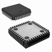
IC UART DUAL 16BYTE 44-PLCC
Manufacturer
National Semiconductor
Datasheet
1.NS16C2552TVAXNOPB.pdf
(44 pages)
Specifications of NS16C2552TVAX/NOPB
Features
Programmable
Number Of Channels
2, DUART
Fifo's
16 Byte
Voltage - Supply
2.97 V ~ 5.5 V
With Auto Flow Control
Yes
With Irda Encoder/decoder
Yes
With Modem Control
Yes
Mounting Type
Surface Mount
Package / Case
44-LCC (J-Lead)
Lead Free Status / RoHS Status
Lead free / RoHS Compliant
Other names
NS16C2552TVAX
Available stocks
Company
Part Number
Manufacturer
Quantity
Price
Company:

Part Number:
NS16C2552TVAX/NOPB
Manufacturer:
Texas Instruments
Quantity:
10 000


Bit
4
3
2
1
0
DTR Output
RTS Output
Bit Name
Loopback
Internal
OUT2
OUT1
Ena
R/W
R/W
R/W
R/W
R/W
R/W
Def
0
0
0
0
0
Internal Loopback Enable
This bit provides a local loopback feature for diagnostic testing of the associated serial channel.
(Refer to Section 7.8 INTERNAL LOOPBACK MODE and Figure 13.)
1 = the transmitter Serial Output (SOUT) is set to the Marking (logic 1) state; the receiver Serial Input
(SIN) is disconnected; the output of the Transmitter Shift Register is looped back into the Receiver
Shift Register input; the four MODEM Control inputs (DSR, CTS, RI, and DCD) are disconnected;
the four MODEM Control outputs (DTR, RTS, OUT1 and OUT2) are internally connected to the four
MODEM Control inputs; and the MODEM Control output pins are forced to their inactive state (high).
In this diagnostic mode, data that is transmitted is immediately received. This feature allows the
processor to verify transmit and receive data paths of the DUART. In this diagnostic mode, the
receiver and transmitter interrupts are fully operational. Their sources are external to the part. The
MODEM Control Interrupts are also operational, but the interrupt sources are now the lower four bits
of the MODEM Control Register instead of the four MODEM Control inputs. The interrupts are still
controlled by the Interrupt Ena
0 = Normal Tx/Rx operation; loopback disabled (default).
Output2
This bit controls the Output 2 (OUT2) signal, which is an auxiliary user-designated output. Bit 3 affects
the OUT2 pin as described below. The function of this bit is multiplexed on a single output pin with
two other functions: BAUDOUT and RXDRY. The OUT2 function is the default function of the pin
after a master reset. See Section 6.12 ALTERNATE FUNCTION REGISTER (AFR) for more
information about selecting one of these 3 pin functions.
1 = Force OUT2 to logic 0.
0 = Force OUT2 to logic 1 (default).
Output1
In normal operation, OUT1 bit is not available as an output.
In internal Loopback Mode (MCR 0x4.4=1) this bit controls the state of the modem input RI in the
MSR bit 6.
1 = MSR 0x06.6 is at logic 1.
0 = MSR 0x06.6 is at logic 0.
RTS Output Control
This bit controls the RTS pin. If modem interface is not used, this output is used as a general purpose
output.
1 = Force RTS pin to logic 0.
0 = Force RTS pin to logic 1(default).
DTR Output Control
This bit controls the DTR pin. If modem interface is not used, this output is used as a general purpose
output.
1 = Force DTR pin to logic 0.
0 = Force DTR pin to logic 1(default).
19
Description
www.national.com
Related parts for NS16C2552TVAX/NOPB
Image
Part Number
Description
Manufacturer
Datasheet
Request
R

Part Number:
Description:
National Semiconductor [8-Bit D/A Converter]
Manufacturer:
National Semiconductor
Datasheet:
Part Number:
Description:
National Semiconductor [Media Coprocessor]
Manufacturer:
National Semiconductor
Datasheet:
Part Number:
Description:
Digitally Controlled Tone and Volume Circuit with Stereo Audio Power Amplifier, Microphone Preamp Stage and National 3D Sound
Manufacturer:
National Semiconductor
Datasheet:
Part Number:
Description:
Digitally Controlled Tone and Volume Circuit with Stereo Audio Power Amplifier, Microphone Preamp Stage and National 3D Sound
Manufacturer:
National Semiconductor
Datasheet:
Part Number:
Description:
AC97 Rev 2 Codec with Sample Rate Conversion and National 3D Sound
Manufacturer:
National Semiconductor
Part Number:
Description:
Manufacturer:
National Semiconductor
Datasheet:
Part Number:
Description:
Manufacturer:
National Semiconductor
Datasheet:
Part Number:
Description:
General Purpose, Low Voltage, Low Power, Rail-to-Rail Output Operational Amplifiers
Manufacturer:
National Semiconductor
Datasheet:
Part Number:
Description:
8-bit 20 MSPS flash A/D converter.
Manufacturer:
National Semiconductor
Datasheet:
Part Number:
Description:
Low Noise Quad Operational Amplifier
Manufacturer:
National Semiconductor
Datasheet:
Part Number:
Description:
Quad Differential Line Receivers
Manufacturer:
National Semiconductor
Datasheet:
Part Number:
Description:
Quad High Speed Trapezoidal? Bus Transceiver
Manufacturer:
National Semiconductor
Datasheet:
Part Number:
Description:
Dual Line Receiver
Manufacturer:
National Semiconductor
Datasheet:
Part Number:
Description:
TTL to 10k ECL Level Translator with Latch
Manufacturer:
National Semiconductor
Datasheet: