NS16C2552TVAX/NOPB National Semiconductor, NS16C2552TVAX/NOPB Datasheet - Page 28
NS16C2552TVAX/NOPB
Manufacturer Part Number
NS16C2552TVAX/NOPB
Description
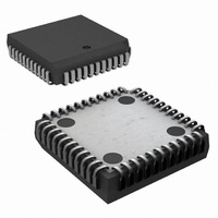
IC UART DUAL 16BYTE 44-PLCC
Manufacturer
National Semiconductor
Datasheet
1.NS16C2552TVAXNOPB.pdf
(44 pages)
Specifications of NS16C2552TVAX/NOPB
Features
Programmable
Number Of Channels
2, DUART
Fifo's
16 Byte
Voltage - Supply
2.97 V ~ 5.5 V
With Auto Flow Control
Yes
With Irda Encoder/decoder
Yes
With Modem Control
Yes
Mounting Type
Surface Mount
Package / Case
44-LCC (J-Lead)
Lead Free Status / RoHS Status
Lead free / RoHS Compliant
Other names
NS16C2552TVAX
Available stocks
Company
Part Number
Manufacturer
Quantity
Price
Company:

Part Number:
NS16C2552TVAX/NOPB
Manufacturer:
Texas Instruments
Quantity:
10 000


www.national.com
time-out interrupt is inactive the time-out timer is reset after a
new character is received or after the CPU reads the Receive
FIFO.
After the first character is read by the host, the next character
is loaded into the RBR and the error flags are loaded into LSR
[4:2].
DMA Mode
In the FIFO mode, the RXRDY asserts when the character in
the Rx FIFO reaches the trigger threshold or timeout occurs.
The RXRDY initiates DMA transfer in a burst mode. The
RXRDY deasserts when the Rx FIFO is completely emptied
and the DMA transfer stops (Figure 5.)
7.3.2 Receive in non-FIFO Mode
Interrupt Mode
In the non-FIFO mode, FCR[0]=0, RBR can be configured to
generate an IIR Receive Data Available interrupt IIR[2] im-
mediately after the first byte is received. Upon interrupt, the
CPU host reads the RBR and clears the interrupt. The inter-
rupt is reasserted when the next character is received. (Figure
6.)
FIGURE 5. RXRDY in DMA Mode 1
20204807
28
DMA Mode
In the non-FIFO mode, the presence of a received character
in RBR causes the assertion of RXRDY at which point DMA
transfer can be initiated. Upon transfer completion RXRDY is
deasserted. DMA transfer stops and awaits for the next char-
acter. (Figure 7.)
7.3.3 Receive Hardware Flow Control
On the line side, RTS signal provides automatic flow control
to prevent data overflow in the Receive FIFO. The RTS is
used to request remote unit to suspend or resume data trans-
mission. This feature is enabled to suit specific application.
The RTS flow control can be enabled by the following steps:
•
•
Enable auto-RTS flow control EFR[6]=1.
The auto-RTS function is initiated by asserting RTS output
pin, MCR[1]=1.
FIGURE 7. RXRDY in DMA Mode 0
FIGURE 6. Rx Non-FIFO Mode
20204808
20204809
Related parts for NS16C2552TVAX/NOPB
Image
Part Number
Description
Manufacturer
Datasheet
Request
R

Part Number:
Description:
National Semiconductor [8-Bit D/A Converter]
Manufacturer:
National Semiconductor
Datasheet:
Part Number:
Description:
National Semiconductor [Media Coprocessor]
Manufacturer:
National Semiconductor
Datasheet:
Part Number:
Description:
Digitally Controlled Tone and Volume Circuit with Stereo Audio Power Amplifier, Microphone Preamp Stage and National 3D Sound
Manufacturer:
National Semiconductor
Datasheet:
Part Number:
Description:
Digitally Controlled Tone and Volume Circuit with Stereo Audio Power Amplifier, Microphone Preamp Stage and National 3D Sound
Manufacturer:
National Semiconductor
Datasheet:
Part Number:
Description:
AC97 Rev 2 Codec with Sample Rate Conversion and National 3D Sound
Manufacturer:
National Semiconductor
Part Number:
Description:
Manufacturer:
National Semiconductor
Datasheet:
Part Number:
Description:
Manufacturer:
National Semiconductor
Datasheet:
Part Number:
Description:
General Purpose, Low Voltage, Low Power, Rail-to-Rail Output Operational Amplifiers
Manufacturer:
National Semiconductor
Datasheet:
Part Number:
Description:
8-bit 20 MSPS flash A/D converter.
Manufacturer:
National Semiconductor
Datasheet:
Part Number:
Description:
Low Noise Quad Operational Amplifier
Manufacturer:
National Semiconductor
Datasheet:
Part Number:
Description:
Quad Differential Line Receivers
Manufacturer:
National Semiconductor
Datasheet:
Part Number:
Description:
Quad High Speed Trapezoidal? Bus Transceiver
Manufacturer:
National Semiconductor
Datasheet:
Part Number:
Description:
Dual Line Receiver
Manufacturer:
National Semiconductor
Datasheet:
Part Number:
Description:
TTL to 10k ECL Level Translator with Latch
Manufacturer:
National Semiconductor
Datasheet: