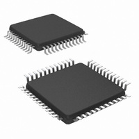
NS16C2752TVS/NOPB National Semiconductor, NS16C2752TVS/NOPB Datasheet - Page 29

NS16C2752TVS/NOPB
Manufacturer Part Number
NS16C2752TVS/NOPB
Description
IC UART DUAL 64BYTE 48-TQFP
Manufacturer
National Semiconductor
Datasheet
1.NS16C2552TVSXNOPB.pdf
(44 pages)
Specifications of NS16C2752TVS/NOPB
Features
Programmable
Number Of Channels
2, DUART
Fifo's
64 Byte
Voltage - Supply
2.97 V ~ 5.5 V
With Auto Flow Control
Yes
With Irda Encoder/decoder
Yes
With Modem Control
Yes
Mounting Type
Surface Mount
Package / Case
48-VFQFP
Lead Free Status / RoHS Status
Lead free / RoHS Compliant
Other names
NS16C2752TVS
Available stocks
Company
Part Number
Manufacturer
Quantity
Price
Company:
Part Number:
NS16C2752TVS/NOPB
Manufacturer:
Texas Instruments
Quantity:
10 000
The auto-RTS assertion and deassertion timing is based up-
on the Rx FIFO trigger level (Table 27 and Table 28).
7.3.4 Receive Flow Control Interrupt
To enable auto RTS interrupt:
•
•
An interrupt is generated when RTS pin makes a transition
from logic 0 to 1; IIR[5] is set to logic 1.
The receive data ready interrupt (IIR[2]) generation timing is
based upon the Rx FIFO trigger level (Table 27 and Table 28).
7.4 TRANSMIT OPERATION
Each serial channel consists of an 8-bit Transmit Shift Reg-
ister (TSR) and a 16-byte (or 64-byte) Transmit FIFO. The
Transmit FIFO includes a 8-bit Transmit Holding Register
(THR). The TSR shifts data out at the 16X internal clock. A bit
time is 16 clock periods. The transmitter begins with a start-
bit followed by data bits, asserts parity-bit if enabled, and adds
the stop-bit(s). The FIFO and TSR status is reported in the
LSR[6:5].
The THR is an 8-bit register providing a data interface to the
host processor. The host writes transmit data to the THR. The
THR is the Transmit FIFO input register in FIFO operation.
The FIFO operation can be enabled by FCR[0]=1. During the
FIFO operation, the FIFO pointer is incremented pointing to
the next FIFO location when a data word is written into the
THR.
7.4.1 Transmit in FIFO Mode
Interrupt mode
In the NS16C2752 FIFO mode (FCR[0]=1), when the Tx FIFO
empty spaces exceed the threshold level the THR empty flag
is set (LSR[5]=1). The THR empty flag generates a TXRDY
interrupt (IIR[1]=1) when the transmit empty interrupt is en-
abled (IER[1]=1). Writing to THR or reading from IIR de-
asserts the interrupt.
There is a two-character hysteresis in interrupt generation.
The host needs to service the interrupt by writing at least two
characters into the Tx FIFO before the next interrupt can be
generated.
The NS16C2552 does not have the FIFO threshold level con-
trol. The interrrupt is generated when the FIFO is completely
empty.
TABLE 27. Auto-RTS HW Flow Control on NS16C2552
Rx Trigger
TABLE 28. Auto-RTS HW flow Control on NS16C2752
Rx Trigger
Enable auto RTS flow control EFR[6]=1.
Enable RTS interrupt IER[6]=1.
Level
Level
14
1
4
8
16
56
60
8
Activation
Activation
INTR Pin
INTR Pin
14
16
56
60
1
4
8
8
Desertion
Desertion
RTS
RTS
14
14
16
56
60
60
2
8
Assertion
Assertion
RTS
RTS
16
56
0
8
0
1
4
8
29
DMA mode
To fully take advantage of the FIFO buffer, the UART is best
operating in DMA mode 1 (FCR[3]=1) when characters are
transferred in bursts. The NS16C2752 has a Tx FIFO thresh-
old level control in register FCR[5:4]. The threshold level sets
the number of empty spaces in the FIFO and determines
when the TXRDY is asserted. If the number of empty spaces
in the FIFO exceeds the threshold, the TXRDY asserts initi-
ating DMA transfers to fill the Tx FIFO. When the empty
spaces in the Tx FIFO becomes zero (i.e., FIFO is full), the
TXRDY deasserts and the DMA transfer stops. TXRDY re-
asserts when empty space exceeds the set threshold, starting
a new DMA transfer cycle. (Figure 9.)
The NS16C2552 does not have the FIFO threshold level con-
trol. The TXRDY is asserted when FIFO is empty and de-
asserted when FIFO is full. It is equivalent of having trigger
threshold set at 16 empty spaces.
FIGURE 8. Tx FIFO Mode
www.national.com
20204810


