LM4937RL/NOPB National Semiconductor, LM4937RL/NOPB Datasheet - Page 21
LM4937RL/NOPB
Manufacturer Part Number
LM4937RL/NOPB
Description
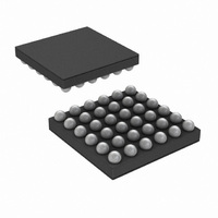
IC AUDIO SUBSYSTM 1.25W 36USMDXT
Manufacturer
National Semiconductor
Series
Boomer®r
Type
Class ABr
Datasheet
1.LM4937TLNOPB.pdf
(42 pages)
Specifications of LM4937RL/NOPB
Output Type
1-Channel (Mono) with Mono and Stereo Headphones
Max Output Power X Channels @ Load
1.25W x 1 @ 8 Ohm; 80mW x 2 @ 32 Ohm
Voltage - Supply
2.7 V ~ 5.5 V
Features
Depop, Differential Inputs, I²C, I²S, Mute, Shutdown, SPI, Volume Control
Mounting Type
Surface Mount
Package / Case
36-MicroSMDxt
Lead Free Status / RoHS Status
Lead free / RoHS Compliant
Other names
LM4937RLTR


If the user needs to obtain a clock unrelated to those described above, the following method is advised. An example of obtaining
11.2896 from 12.000MHz is shown below.
Choose a small range of P so that the VCO frequency is swept between 45 and 55MHz (or 60-80MHz if VCOFAST is used).
Remembering that the P divider can divide by half integers. So for P = 4.0
accurate N and N_MOD can be calculated by:
N = FLOOR(((Fout/Fin)*(P*M)),1)
N_MOD = ROUND(32*((((Fout)/Fin)*(P*M)-N),0)
This shows that setting M = 11.5, N = 75 N_MOD = 47 P = 7 gives a comparison frequency of just over 1MHz, a VCO frequency
of just under 80MHz (so VCO_FAST must be set) and an output frequency of 11.289596 which gives a sample rate of
44.099985443kHz, or accurate to 0.33 ppm.
Care must be taken when synchronization of isochronous data is not possible, i.e. when the PLL has to be used in the above mode.
The I2S should be master on the LM4937 so that the data source can support appropriate SRC as required. This method should
only be used with data being read on demand to eliminate sample rate mismatch problems.
Where a system clock exists at an integer multiple of the required DAC clock rate it is preferable to use this rather than the PLL.
The LM4937 is designed to work in 8,12,16,24,32, and 48kHz modes from a 12MHz clock without the use of the PLL. This saves
power and reduces clock jitter.
Clock Configuration Register
This register is used to control the multiplexers and clock R divider in the clock module.
CLOCK (09h) (Set = logic 1, Clear = logic 0)
Bits
0
1
2
3
AUDIO_CLK_SEL
FAST_CLOCK
PLL_ENABLE
PLL_INPUT
Register
DAC_CLK_SEL
FAST_CLOCK
PLL_INPUT
Selects which clock is passed to the audio sub-system
0
1
0
1
0
1
Programs the PLL input multiplexer to select:
If set enables the PLL. (MODES 4–7 only)
21
If set master clock is divided by two.
→
Description
7.0 sweep the M inputs from 2.5
MCLK Frequency
PLL Input Source
DAC Sub-system
I
2
Input Source
Divided by 2
S Input Clock
PLL Output
PLL Input
Normal
MCLK
→
24. The most
www.national.com
Related parts for LM4937RL/NOPB
Image
Part Number
Description
Manufacturer
Datasheet
Request
R

Part Number:
Description:
Manufacturer:
National Semiconductor
Datasheet:
Part Number:
Description:
National Semiconductor [8-Bit D/A Converter]
Manufacturer:
National Semiconductor
Datasheet:
Part Number:
Description:
National Semiconductor [Media Coprocessor]
Manufacturer:
National Semiconductor
Datasheet:
Part Number:
Description:
Digitally Controlled Tone and Volume Circuit with Stereo Audio Power Amplifier, Microphone Preamp Stage and National 3D Sound
Manufacturer:
National Semiconductor
Datasheet:
Part Number:
Description:
Digitally Controlled Tone and Volume Circuit with Stereo Audio Power Amplifier, Microphone Preamp Stage and National 3D Sound
Manufacturer:
National Semiconductor
Datasheet:
Part Number:
Description:
AC97 Rev 2 Codec with Sample Rate Conversion and National 3D Sound
Manufacturer:
National Semiconductor
Part Number:
Description:
Manufacturer:
National Semiconductor
Datasheet:
Part Number:
Description:
Manufacturer:
National Semiconductor
Datasheet:
Part Number:
Description:
General Purpose, Low Voltage, Low Power, Rail-to-Rail Output Operational Amplifiers
Manufacturer:
National Semiconductor
Datasheet:
Part Number:
Description:
8-bit 20 MSPS flash A/D converter.
Manufacturer:
National Semiconductor
Datasheet:
Part Number:
Description:
Low Noise Quad Operational Amplifier
Manufacturer:
National Semiconductor
Datasheet:
Part Number:
Description:
Quad Differential Line Receivers
Manufacturer:
National Semiconductor
Datasheet:
Part Number:
Description:
Quad High Speed Trapezoidal? Bus Transceiver
Manufacturer:
National Semiconductor
Datasheet:
Part Number:
Description:
Dual Line Receiver
Manufacturer:
National Semiconductor
Datasheet: