LM4937RL/NOPB National Semiconductor, LM4937RL/NOPB Datasheet - Page 35
LM4937RL/NOPB
Manufacturer Part Number
LM4937RL/NOPB
Description
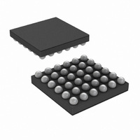
IC AUDIO SUBSYSTM 1.25W 36USMDXT
Manufacturer
National Semiconductor
Series
Boomer®r
Type
Class ABr
Datasheet
1.LM4937TLNOPB.pdf
(42 pages)
Specifications of LM4937RL/NOPB
Output Type
1-Channel (Mono) with Mono and Stereo Headphones
Max Output Power X Channels @ Load
1.25W x 1 @ 8 Ohm; 80mW x 2 @ 32 Ohm
Voltage - Supply
2.7 V ~ 5.5 V
Features
Depop, Differential Inputs, I²C, I²S, Mute, Shutdown, SPI, Volume Control
Mounting Type
Surface Mount
Package / Case
36-MicroSMDxt
Lead Free Status / RoHS Status
Lead free / RoHS Compliant
Other names
LM4937RLTR


is required. S2 connects the center amplifer HPCOUT to the
headphone ring when in OCL mode. S4 connects the center
ring to GND when cap-coupled mode is desired. S4 must be
removed for OCL mode to function properly. Jumper settings
for each mode:
OCL (CD_6 = 1)
S1 = ON
S2 = ON
S3 = ON
S4 = OFF
Cap-Coupled (CD_6 = 0)
S1 = OFF
S2 = OFF
S3 = OFF
S4 = ON
PLL FILTER CONFIGURATION
The LM4937 demo board comes with a simple filter setup by
connecting jumpers S5 and S6. Removing these and con-
necting jumpers S7 and S8 will allow for an alternate PLL filter
configuration to be used at R2 and C23.
ON-BOARD SPDIF RECEIVER
The SPDIF receiver present on the LM4937 demo board al-
lows quick demonstration of the capabilities of the LM4937 by
using the common SPDIF output found on most CD/DVD
players today. There are some limitations in its useage, as the
receiver will not work with digital supplies of less than 3.0V
and analog supplies of less than 4V. This means low analog
35
supply voltage testing of the LM4937 must be done on the
external digital bus.
The choice of using on-board or external digital bus is made
usign jumpers S23, S24, S26, and S27 as described above.
S25 selects whether the Toslink or Coaxial SPDIF input is
used. The top two pins connects the toslink, the bottom two
connect the coaxial input.
Power on the digital side is routed through S20 (connecting
to the other digital supplies), while on the analog side it is
interrupted by S21. Both jumpers must be in place for the re-
ceiver to function. The part is already configured for I2S
standard outputs. Jumper S28 allows the DATA output to be
pulled either high or low. Default is high (jumper on right two
pins).
It may be necessary to quickly toggle S29 to reset the receiver
and start it working upon initial power up.. A quick short across
S29 should clear this condition.
LM4937 I
Convenient graphical user interface software is available for
demonstration purposes of the LM4937. It allows for either
SPI or I
to a Windows computer. Control options include all mode and
output settings, volume controls, PLL and DAC setup, FIR
setting and on-the-fly adjustment by an easy to use graphical
interface. An advanced option is also present to allow direct,
register-level commands. Software is available from
www.national.com and is compatible with Windows operating
systems of Windows 98 or more (with USB support) with the
latest .NET updates from Microsoft.
2
C control via either USB or parallel port connections
2
C/SPI INTERFACE SOFTWARE
www.national.com
Related parts for LM4937RL/NOPB
Image
Part Number
Description
Manufacturer
Datasheet
Request
R

Part Number:
Description:
Manufacturer:
National Semiconductor
Datasheet:
Part Number:
Description:
National Semiconductor [8-Bit D/A Converter]
Manufacturer:
National Semiconductor
Datasheet:
Part Number:
Description:
National Semiconductor [Media Coprocessor]
Manufacturer:
National Semiconductor
Datasheet:
Part Number:
Description:
Digitally Controlled Tone and Volume Circuit with Stereo Audio Power Amplifier, Microphone Preamp Stage and National 3D Sound
Manufacturer:
National Semiconductor
Datasheet:
Part Number:
Description:
Digitally Controlled Tone and Volume Circuit with Stereo Audio Power Amplifier, Microphone Preamp Stage and National 3D Sound
Manufacturer:
National Semiconductor
Datasheet:
Part Number:
Description:
AC97 Rev 2 Codec with Sample Rate Conversion and National 3D Sound
Manufacturer:
National Semiconductor
Part Number:
Description:
Manufacturer:
National Semiconductor
Datasheet:
Part Number:
Description:
Manufacturer:
National Semiconductor
Datasheet:
Part Number:
Description:
General Purpose, Low Voltage, Low Power, Rail-to-Rail Output Operational Amplifiers
Manufacturer:
National Semiconductor
Datasheet:
Part Number:
Description:
8-bit 20 MSPS flash A/D converter.
Manufacturer:
National Semiconductor
Datasheet:
Part Number:
Description:
Low Noise Quad Operational Amplifier
Manufacturer:
National Semiconductor
Datasheet:
Part Number:
Description:
Quad Differential Line Receivers
Manufacturer:
National Semiconductor
Datasheet:
Part Number:
Description:
Quad High Speed Trapezoidal? Bus Transceiver
Manufacturer:
National Semiconductor
Datasheet:
Part Number:
Description:
Dual Line Receiver
Manufacturer:
National Semiconductor
Datasheet: