LM49370RL/NOPB National Semiconductor, LM49370RL/NOPB Datasheet - Page 52
LM49370RL/NOPB
Manufacturer Part Number
LM49370RL/NOPB
Description
IC AUDIO SUBSYSTEM 1.2W 49USMDXT
Manufacturer
National Semiconductor
Series
Boomer®, PowerWise®r
Type
Class Dr
Datasheet
1.LM49370RLNOPB.pdf
(100 pages)
Specifications of LM49370RL/NOPB
Output Type
1-Channel (Mono) with Mono and Stereo Headphones
Max Output Power X Channels @ Load
1.2W x 1 @ 8 Ohm; 52mW x 2 @ 16 Ohm
Voltage - Supply
2.5 V ~ 5.5 V
Features
3D, Depop, I²C, I²S, Microphone, Mute, PCM, Shutdown, SPI, Standby, Volume Control
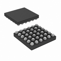
Mounting Type
Surface Mount
Package / Case
49-MicroSMDxt
Dc
07+
For Use With
LM49370RLEVAL - BOARD EVALUATION LM49370RL
Lead Free Status / RoHS Status
Lead free / RoHS Compliant
Other names
LM49370RLTR


www.national.com
Bits
12.35 PCM PORT MODE CONFIGURATION REGISTER
This register is used to control the audio data interfaces.
0
1
3
4
5
6
7
PCM_ALAW_μLAW
PCM_CLOCK_SOURCE DAC or ADC Clock 0 = DAC, 1 = ADC (Note 32)
PCM_SDO_LSB_HZ
PCM_COMPAND
PCM_SYNC_MS
PCM_OUT_ENB
PCM_IN_ENB
Field
If set, the PCM output bus is enabled. If this bit is cleared, thr PCM output will be tristate and all
RX clocks will be gated.
If set, the PCM input is enabled. If this bit is cleared, the PCM input is ignored and TX clocks are
generated.
If set, PCM_SYNC generation is enabled and is driven by the device (Master).
If set, when the PCM port has run out of bits to transmit, it will tristate the SDO output.
If set, the data sent to the PCM port is companded and the PCM data received by the PCM receiver
is treated as companded data.
If PCM_ COMPAND is set, then the data across the PCM interface to the DAC and from the ADC
is companded as follows:
FIGURE 13. PCM Audio Port CLOCK/SYNC Options
PCM_ALAW_μLAW
TABLE 35. PCM MODE (0x1Ch)
0
1
52
Description
Commanding Type
μ-LAW
A-Law
201917r1
Related parts for LM49370RL/NOPB
Image
Part Number
Description
Manufacturer
Datasheet
Request
R

Part Number:
Description:
Audio Sub-system With An Ultra Low Emi, Spread Spectrum, Class D Loudspeaker Amplifier, A Dual-mode Stereo Headphone Amplifier, And A Dedicated Pcm Interface For Bluetooth Transceivers
Manufacturer:
National Semiconductor Corporation
Datasheet:

Part Number:
Description:
National Semiconductor [8-Bit D/A Converter]
Manufacturer:
National Semiconductor
Datasheet:
Part Number:
Description:
National Semiconductor [Media Coprocessor]
Manufacturer:
National Semiconductor
Datasheet:
Part Number:
Description:
Digitally Controlled Tone and Volume Circuit with Stereo Audio Power Amplifier, Microphone Preamp Stage and National 3D Sound
Manufacturer:
National Semiconductor
Datasheet:
Part Number:
Description:
Digitally Controlled Tone and Volume Circuit with Stereo Audio Power Amplifier, Microphone Preamp Stage and National 3D Sound
Manufacturer:
National Semiconductor
Datasheet:
Part Number:
Description:
AC97 Rev 2 Codec with Sample Rate Conversion and National 3D Sound
Manufacturer:
National Semiconductor
Part Number:
Description:
Manufacturer:
National Semiconductor
Datasheet:
Part Number:
Description:
Manufacturer:
National Semiconductor
Datasheet:
Part Number:
Description:
General Purpose, Low Voltage, Low Power, Rail-to-Rail Output Operational Amplifiers
Manufacturer:
National Semiconductor
Datasheet:
Part Number:
Description:
8-bit 20 MSPS flash A/D converter.
Manufacturer:
National Semiconductor
Datasheet:
Part Number:
Description:
Low Noise Quad Operational Amplifier
Manufacturer:
National Semiconductor
Datasheet:
Part Number:
Description:
Quad Differential Line Receivers
Manufacturer:
National Semiconductor
Datasheet:
Part Number:
Description:
Quad High Speed Trapezoidal? Bus Transceiver
Manufacturer:
National Semiconductor
Datasheet:
Part Number:
Description:
Dual Line Receiver
Manufacturer:
National Semiconductor
Datasheet: