SA58672TK,138 NXP Semiconductors, SA58672TK,138 Datasheet - Page 13
SA58672TK,138
Manufacturer Part Number
SA58672TK,138
Description
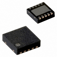
IC AMP AUDIO 3W MONO D 10HVSON
Manufacturer
NXP Semiconductors
Type
Class Dr
Datasheet
1.SA58672UK027.pdf
(27 pages)
Specifications of SA58672TK,138
Output Type
1-Channel (Mono)
Package / Case
10-HVSON
Max Output Power X Channels @ Load
3W x 1 @ 4 Ohm
Voltage - Supply
2 V ~ 5.5 V
Features
Differential Inputs, Short-Circuit and Thermal Protection, Shutdown
Mounting Type
Surface Mount
Product
Class-D
Output Power
3 W
Common Mode Rejection Ratio (min)
69 dB
Thd Plus Noise
0.08 %
Operating Supply Voltage
3 V, 5 V
Supply Current
3.4 mA
Maximum Power Dissipation
3.12 mW
Maximum Operating Temperature
+ 85 C
Mounting Style
SMD/SMT
Audio Load Resistance
8 Ohms
Input Signal Type
Differential
Minimum Operating Temperature
- 40 C
Output Signal Type
Differential, Single
Supply Type
Single
Supply Voltage (max)
5.5 V
Supply Voltage (min)
2 V
Lead Free Status / RoHS Status
Lead free / RoHS Compliant
Lead Free Status / RoHS Status
Lead free / RoHS Compliant, Lead free / RoHS Compliant
Other names
935286769138
SA58672TK-T
SA58672TK-T
SA58672TK-T
SA58672TK-T


NXP Semiconductors
11. Application information
SA58672_4
Product data sheet
11.1 Power supply decoupling considerations
11.2 Voltage gain
11.3 Input capacitor selection
The SA58672 is a mono class-D audio amplifier that requires proper power supply
decoupling to ensure the rated performance for THD+N and power efficiency. To decouple
high frequency transients, power supply spikes and digital noise on the power bus line, a
low Equivalent Series Resistance (ESR) capacitor, of typically 1 F is placed as close as
possible to the PVDD terminals of the device. It is important to place the decoupling
capacitor at the power pins of the device because any resistance or inductance in the
PCB trace between the device and the capacitor can cause a loss in efficiency. Additional
decoupling using a larger capacitor, 4.7 F or greater may be done on the power supply
connection on the PCB to filter low frequency signals. Usually this is not required due to
high PSRR of the device.
The SA58672 is comprised of an analog amplifier stage and a comparator stage. The
output of the analog amplifier stage is compared with the periodic ramp signal from the
sawtooth ramp generator. The resulting output of the comparator is a Pulse Width
Modulated (PWM) signal. The final stage is a power NMOS and PMOS H-bridge that
converts the PWM into a high power output signal capable of driving low-impedance
loads.
The input resistor, R
The SA58672 does not require input coupling capacitors when used with a differential
audio source that is biased from 0.5 V to V
be biased within the common-mode input voltage range. If high-pass filtering is required
or if it is driven using a single-ended source, input coupling capacitors are required.
The 3 dB cut-off frequency created by the input coupling capacitor and the input resistors
is calculated by
Using an input resistor of 150 k , the gain is set to 2 V/V. At this gain setting, for input
capacitor values from 220 nF to 2.2 F, the 3 dB cut-off frequency may be set between
22 Hz and 220 Hz. Since the values of the input coupling capacitor and the input resistor
affects the low frequency performance of the audio amplifier, it is important to consider in
the system design. Small speakers in wireless and cellular phones usually do not respond
well to low frequency signals. Their low frequency response may be only 600 Hz; typically
1 kHz. Thus, the 3 dB cut-off frequency should be increased to block the low frequency
signals to the speakers.
Gain
f
–
3dB
=
=
2 150 k
-------------------------- -
----------------------------- -
2
R
R
1
i
i
Equation
C
i
i
sets the gain of the amplifier according to
Rev. 04 — 8 June 2009
2:
DD
0.8 V. In other words, the input signal must
3.0 W mono class-D audio amplifier
Equation
SA58672
© NXP B.V. 2009. All rights reserved.
1:
13 of 27
(1)
(2)
Related parts for SA58672TK,138
Image
Part Number
Description
Manufacturer
Datasheet
Request
R

Part Number:
Description:
Manufacturer:
NXP Semiconductors
Datasheet:
Part Number:
Description:
NXP Semiconductors designed the LPC2420/2460 microcontroller around a 16-bit/32-bitARM7TDMI-S CPU core with real-time debug interfaces that include both JTAG andembedded trace
Manufacturer:
NXP Semiconductors
Datasheet:

Part Number:
Description:
NXP Semiconductors designed the LPC2458 microcontroller around a 16-bit/32-bitARM7TDMI-S CPU core with real-time debug interfaces that include both JTAG andembedded trace
Manufacturer:
NXP Semiconductors
Datasheet:
Part Number:
Description:
NXP Semiconductors designed the LPC2468 microcontroller around a 16-bit/32-bitARM7TDMI-S CPU core with real-time debug interfaces that include both JTAG andembedded trace
Manufacturer:
NXP Semiconductors
Datasheet:
Part Number:
Description:
NXP Semiconductors designed the LPC2470 microcontroller, powered by theARM7TDMI-S core, to be a highly integrated microcontroller for a wide range ofapplications that require advanced communications and high quality graphic displays
Manufacturer:
NXP Semiconductors
Datasheet:
Part Number:
Description:
NXP Semiconductors designed the LPC2478 microcontroller, powered by theARM7TDMI-S core, to be a highly integrated microcontroller for a wide range ofapplications that require advanced communications and high quality graphic displays
Manufacturer:
NXP Semiconductors
Datasheet:
Part Number:
Description:
The Philips Semiconductors XA (eXtended Architecture) family of 16-bit single-chip microcontrollers is powerful enough to easily handle the requirements of high performance embedded applications, yet inexpensive enough to compete in the market for hi
Manufacturer:
NXP Semiconductors
Datasheet:
Part Number:
Description:
The XA-S3 device is a member of Philips Semiconductors? XA(eXtended Architecture) family of high performance 16-bitsingle-chip microcontrollers
Manufacturer:
NXP Semiconductors
Datasheet:

Part Number:
Description:
The NXP BlueStreak LH75401/LH75411 family consists of two low-cost 16/32-bit System-on-Chip (SoC) devices
Manufacturer:
NXP Semiconductors
Datasheet:
Part Number:
Description:
The NXP LPC3130/3131 combine an 180 MHz ARM926EJ-S CPU core, high-speed USB2
Manufacturer:
NXP Semiconductors
Datasheet:
Part Number:
Description:
The NXP LPC3141 combine a 270 MHz ARM926EJ-S CPU core, High-speed USB 2
Manufacturer:
NXP Semiconductors
Part Number:
Description:
The NXP LPC3143 combine a 270 MHz ARM926EJ-S CPU core, High-speed USB 2
Manufacturer:
NXP Semiconductors

Part Number:
Description:
The NXP LPC3152 combines an 180 MHz ARM926EJ-S CPU core, High-speed USB 2
Manufacturer:
NXP Semiconductors
Part Number:
Description:
The NXP LPC3154 combines an 180 MHz ARM926EJ-S CPU core, High-speed USB 2
Manufacturer:
NXP Semiconductors