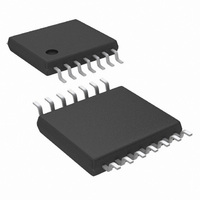
LM48100QMH/NOPB National Semiconductor, LM48100QMH/NOPB Datasheet - Page 15

LM48100QMH/NOPB
Manufacturer Part Number
LM48100QMH/NOPB
Description
IC AMP AUDIO PWR 1.6W 14ETSSOP
Manufacturer
National Semiconductor
Series
Boomer®, PowerWise®r
Type
Class ABr
Datasheet
1.LM48100QMHENOPB.pdf
(24 pages)
Specifications of LM48100QMH/NOPB
Output Type
1-Channel (Mono)
Max Output Power X Channels @ Load
1.6W x 1 @ 8 Ohm
Voltage - Supply
3 V ~ 5.5 V
Features
Depop, I²C, Input Multiplexer, Short-Circuit and Thermal Protection, Shutdown, Volume Control
Mounting Type
Surface Mount
Package / Case
14-TSSOP Exposed Pad, 14-eTSSOP 14-HTSSOP
Amplifier Class
AB
No. Of Channels
1
Output Power
1.3W
Supply Voltage Range
3V To 5.5V
Load Impedance
8ohm
Operating Temperature Range
-40°C To +105°C
Amplifier Case Style
TSSOP
Rohs Compliant
Yes
Lead Free Status / RoHS Status
Lead free / RoHS Compliant
Other names
LM48100QMH
GENERAL AMPLIFIER FUNCTION
Bridge Configuration Explained
The LM48100Q is designed to drive a load differentially, a
configuration commonly referred to as a bridge-tied load
(BTL). The BTL configuration differs from the single-ended
configuration, where one side of the load is connected to
ground. A BTL amplifier offers advantages over a single-end-
ed device. By driving the load differentially, the output voltage
is doubled, compared to a single-ended amplifier under sim-
ilar conditions. This doubling of the output voltage leads to a
quadrupling of the output power. For example, the theoretical
maximum output power for a single-ended amplifier driving
8Ω and operating from a 5V supply is 158mW, while the the-
oretical maximum output power for a BTL amplifier operating
under the same conditions is 633mW. Since the amplifier out-
puts are both biased about V
across the load, eliminating the DC blocking capacitors re-
quired by single-ended, single-supply amplifiers.
Input Mixer/Multiplexer
The LM48100Q features an input mixer/multiplexer controlled
through the I
input, or the combination of both inputs to appear at the device
output. Bits B2 (INPUT_1) and B3 (INPUT_2) of the Mode
Control Register select the individual input channels. Set IN-
PUT_1 = 1 to select the audio signal on IN1. Set INPUT_2 =
1 to select the audio signal on IN2. Setting both INPUT_1 and
INPUT_2 = 1 mixes V
the result as a mono signal (Table 7).
OUTPUT FAULT DETECTION
Output Short to Supplies (V
With a standard speaker load (6Ω - 100Ω) connected be-
tween OUTA and OUTB, the LM48100Q can detect a short
between the outputs and either V
tected if the impedance between either OUTA or OUTB and
V
impedance between BOTH OUTA and OUTB and either
V
the amplifier outputs are disabled and FAULT is driven low.
No short is detected if the impedance between either output
and V
DD
DD
INPUT_1
or GND is less than 6kΩ. Under either of these conditions,
or GND is less than 3kΩ. A short is also detected if the
DD
0
1
0
1
or GND is greater than 7.5kΩ. Likewise, no short is
TABLE 6. Input Multiplexer Control
2
C interface. The mixer/multiplexer allows either
INPUT_2
0
0
1
1
IN1
and V
DD
DD
IN2
MUTE. No input selected
/2, there is no net DC voltage
, and the LM48100Q outputs
or GND)
LM48100Q OUTPUT
DD
or GND. A short is de-
IN1 ONLY
IN2 ONLY
IN1 + IN2
15
detected if the impedance between BOTH outputs and V
GND is greater than 15kΩ.
Output Short Circuit and Open Circuit Detection
The LM48100Q can detect whether the amplifier outputs have
been shorted together or, an output open circuit condition has
occurred. An output short circuit is detected if the impedance
between OUTA and OUTB is less than 2Ω. An open circuit is
detected if the impedance between OUTA and OUTB is
greater than 200Ω. Under either of these conditions, the am-
plifier outputs are disabled and FAULT is driven low. The
device remains in normal operation if the impedance between
OUTA and OUTB is in the range of 6Ω to 100Ω. The output
open circuit test is only performed during the initial diagnostic
sequence during power up, or when DG_ENABLE is set to 1.
Output Over-Current Detection
The LM48100Q has two over current detection modes, a fixed
current limit, and a supply dependent current limit. Bit B1
(ILIMIT) of the Diagnostic Control Register selects the over-
current detection mode. Set ILIMIT = 0 to select a fixed current
limit of 1.47A (typ). Set ILIMIT = 1 to select the supply de-
pendent current limit mode. In supply dependent mode, the
current limit is determined by equation (1):
If the output current exceeds the current limit, the device out-
puts are disabled and FAULT is driven low. The output over-
current detection circuitry remains active when the diagnos-
tics have been disabled (DG_EN = 0).
Thermal Overload Detection
The LM48100Q has thermal overload threshold of 170°C
(typ). If the die temperature exceeds 170°C, the outputs are
disabled and FAULT is driven low. The thermal overload de-
tection circuitry remains active when the diagnostics have
been disabled (DG_EN = 0).
OPEN FAULT OUTPUT
The LM48100Q features an open drain, fault indication out-
put, FAULT , that asserts when a fault condition is detected
by the device. FAULT goes low when either an output short,
output open, over current, or thermal overload fault is detect-
ed, and the diagnostic test is not ignored, see FAULT DE-
TECTION CONTROL section. FAULT remains low even after
the fault condition has been cleared and the diagnostic tests
are repeated. Toggle DG_RESET to clear FAULT .
Connect a 1.5kΩ or higher pull-up resistor between FAULT
and V
DD
.
I
SHTCKT
= 0.264 x V
DD
(A)
www.national.com
DD
(1)
or


