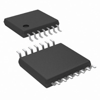
LM48100QMH/NOPB National Semiconductor, LM48100QMH/NOPB Datasheet - Page 17

LM48100QMH/NOPB
Manufacturer Part Number
LM48100QMH/NOPB
Description
IC AMP AUDIO PWR 1.6W 14ETSSOP
Manufacturer
National Semiconductor
Series
Boomer®, PowerWise®r
Type
Class ABr
Datasheet
1.LM48100QMHENOPB.pdf
(24 pages)
Specifications of LM48100QMH/NOPB
Output Type
1-Channel (Mono)
Max Output Power X Channels @ Load
1.6W x 1 @ 8 Ohm
Voltage - Supply
3 V ~ 5.5 V
Features
Depop, I²C, Input Multiplexer, Short-Circuit and Thermal Protection, Shutdown, Volume Control
Mounting Type
Surface Mount
Package / Case
14-TSSOP Exposed Pad, 14-eTSSOP 14-HTSSOP
Amplifier Class
AB
No. Of Channels
1
Output Power
1.3W
Supply Voltage Range
3V To 5.5V
Load Impedance
8ohm
Operating Temperature Range
-40°C To +105°C
Amplifier Case Style
TSSOP
Rohs Compliant
Yes
Lead Free Status / RoHS Status
Lead free / RoHS Compliant
Other names
LM48100QMH
SHUTDOWN FUNCTION
The LM48100Q features an I
down mode that disables the device, reducing quiescent cur-
rent consumption to 0.01μA. Set bit B4 (POWER_ON) in the
Mode Control Register to 0 to disable the device. Set B0 to 1
to enable the device.
POWER DISSIPATION
The increase in power delivered by a BTL amplifier leads to
a direct increase in internal power dissipation. The maximum
power dissipation for a BTL amplifier for a given supply volt-
age and load is given by equation (2):
The maximum power dissipation of the TSSOP package is
calculated by equation (3):
where T
θ
mum Ratings.
If the power dissipation for a given operating condition ex-
ceeds the package maximum, either decrease the ambient
temperature, increase air flow, add heat sinking to the device,
or increase the load impedance and/or supply voltage. The
LM48100Q TSSOP package features an exposed die attach
pad (DAP) that can be used to increase the maximum power
dissipation of the package, see Exposed DAP Mounting Con-
siderations.
The LM48100Q features thermal overload protection that dis-
ables the amplifier output stage when the die temperature
exceeds +170°C. See the Thermal Overload Detection sec-
tion.
JA
is the thermal resistance specified in the Absolute Maxi-
P
JMAX
DMAX (PKG)
P
DMAX
is 150°C, T
= 4 x V
= T
JMAX
DD
A
2
/ 2
— T
is the ambient temperature and
π
2
C selectable low power shut-
2
A
R
L
/ θ
JA
(Watts)
(Watts)
(2)
(3)
17
PROPER SELECTION OF EXTERNAL COMPONENTS
Power Supply Bypassing/Filtering
Proper power supply bypassing is critical for low noise per-
formance and high PSRR. Place the supply bypass capaci-
tors as close to the device as possible. Place a 1µF ceramic
capacitor from V
be added as required.
Input Capacitor Selection
Input capacitors may be required for some applications, or
when the audio source is single-ended. Input capacitors block
the DC component of the audio signal, eliminating any conflict
between the DC component of the audio source and the bias
voltage of the LM48100Q. The input capacitors create a high-
pass filter with the input resistors R
high-pass filter is found using Equation (4) below.
Where the value of R
tics Table.
High pass filtering the audio signal helps protect the speakers.
When the LM48100Q is using a single-ended source, power
supply noise on the ground is seen as an input signal. Setting
the high-pass filter point above the power supply noise fre-
quencies, filters out the noise such that it is not amplified and
heard on the output. Capacitors with a tolerance of 10% or
better are recommended for impedance matching and im-
proved PSRR.
Bias Capacitor Selection
The LM48100Q internally generates a V
bias voltage. The BIAS capacitor C
THD+N by reducing noise at the BIAS node. Use a 2.2µF ce-
ramic placed as close to the device as possible.
f = 1 / 2
DD
to GND. Additional bulk capacitance may
IN
π
is given in the Electrical Characteris-
R
IN
C
IN
(Hz)
BIAS
IN
. The -3dB point of the
, improves PSRR and
DD
/2 common-mode
www.national.com
(4)


