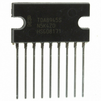
TDA8945S/N1,112 NXP Semiconductors, TDA8945S/N1,112 Datasheet

TDA8945S/N1,112
Specifications of TDA8945S/N1,112
935262856112
TDA8945SU
Available stocks
Related parts for TDA8945S/N1,112
TDA8945S/N1,112 Summary of contents
Page 1
TDA8945S 15 W mono Bridge Tied Load (BTL) audio amplifier Rev. 02 — 7 April 2000 1. General description The TDA8945S is a single-channel audio power amplifier with an output power (BTL) amplifier with ...
Page 2
Philips Semiconductors Table 1: Symbol Parameter P o THD G v SVRR 5. Ordering information Table 2: Type number Package TDA8945S 6. Block diagram idth Fig 1. Block diagram. 9397 750 06866 Product specification Quick reference data …continued Conditions output ...
Page 3
Philips Semiconductors 7. Pinning information 7.1 Pinning Fig 2. Pin configuration. 7.2 Pin description Table 3: Symbol OUT V CC OUT+ IN+ IN SVR MODE GND n.c. 8. Functional description The TDA8945S is a mono BTL audio power amplifier capable ...
Page 4
Philips Semiconductors 8.1 Input configuration The TDA8945S inputs can be driven symmetrical (floating) as well as asymmetrical. In the asymmetrical mode one input pin is connected via a capacitor to the signal ground which should be as close as possible ...
Page 5
Philips Semiconductors 8.2.2 Headroom Typical CD music requires at least 12 dB (factor 15.85) dynamic headroom – compared to the average power output – for transferring the loudest parts without distortion Average Listening Level (ALL) – music power ...
Page 6
Philips Semiconductors 8.4 Supply Voltage Ripple Rejection (SVRR) The SVRR is measured with an electrolytic capacitor pin SVR at a bandwidth kHz. of the frequency. A larger capacitor value on the ...
Page 7
Philips Semiconductors 11. Static characteristics Table 7: Static characteristics amb L Symbol Parameter V supply voltage CC I quiescent supply current q I standby supply current ...
Page 8
Philips Semiconductors 12. Dynamic characteristics Table 8: Dynamic characteristics kHz amb L Symbol Parameter P output power o THD total harmonic distortion G ...
Page 9
Philips Semiconductors handbook, halfpage Fig 6. Total harmonic distortion as function of output power. 10 handbook, full pagewidth THD (%) bandpass filter applied. Fig 7. Total harmonic distortion as function of ...
Page 10
Philips Semiconductors 20 handbook, halfpage THD = 10%. Fig 8. Output power as function of supply voltage. 100 handbook, halfpage (%) ...
Page 11
Philips Semiconductors 0 handbook, full pagewidth SVRR (dB 707 mV (RMS); no bandpass filter applied ripple Curve A: inputs short-circuited ...
Page 12
Philips Semiconductors 13. Internal circuitry Table 9: Pin 4 and 5 1 and 9397 750 06866 Product specification Internal circuitry Symbol Equivalent circuit IN+ and IN 5 OUT and OUT+ MODE 7 SVR Rev. 02 — 7 ...
Page 13
Philips Semiconductors 14. Application information handbook, full pagewidth 220 Symmetrical C i input 220 nF 220 Asymmetrical C i input 220 nF signal V CC GND MICROCONTROLLER MODE ...
Page 14
Philips Semiconductors idth Fig 14. Printed-circuit board layout (single-sided); components view. 14.1.2 Power supply decoupling Proper supply bypassing is critical for low-noise performance and high supply voltage ripple rejection. The respective capacitor locations should be as close as possible to ...
Page 15
Philips Semiconductors 14.2 Thermal behaviour and heatsink calculation The measured maximum thermal resistance of the IC package, A calculation for the heatsink can be made, with the following parameters: T amb(max j(max) R th(tot) including the heatsink. ...
Page 16
Philips Semiconductors 16. Package outline SIL9P: plastic single in-line power package; 9 leads DIMENSIONS (mm are the original dimensions UNIT max. max. 4.6 0.75 mm 2.0 1.1 4.4 ...
Page 17
Philips Semiconductors 17. Soldering 17.1 Introduction to soldering through-hole mount packages This text gives a brief insight to wave, dip and manual soldering. A more in-depth account of soldering ICs can be found in our Data Handbook IC26; Integrated Circuit ...
Page 18
Philips Semiconductors 18. Revision history Table 11: Revision history Rev Date CPCN Description 02 20000407 - Product specification; second version; supersedes initial version TDA8945S- April 1999 (9397 750 04878). Modifications: • Table 1 on page • Ordering options ...
Page 19
Philips Semiconductors 19. Data sheet status Datasheet status Product status Definition Objective specification Development This data sheet contains the design target or goal specifications for product development. Specification may change in any manner without notice. Preliminary specification Qualification This data ...
Page 20
Philips Semiconductors Philips Semiconductors - a worldwide company Argentina: see South America Australia: Tel. +61 2 9704 8141, Fax. +61 2 9704 8139 Austria: Tel. +43 160 101, Fax. +43 160 101 1210 Belarus: Tel. +375 17 220 0733, Fax. ...
Page 21
Philips Semiconductors Contents 1 General description . . . . . . . . . . . . . . . . . . . . . . 1 2 Features . . . . . . . . . ...


