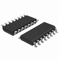
TDA8559T/N1,518 NXP Semiconductors, TDA8559T/N1,518 Datasheet - Page 6

TDA8559T/N1,518
Manufacturer Part Number
TDA8559T/N1,518
Description
IC AMP AUDIO .14W MONO AB 16SOIC
Manufacturer
NXP Semiconductors
Type
Class ABr
Datasheet
1.TDA8559TN1512.pdf
(36 pages)
Specifications of TDA8559T/N1,518
Package / Case
16-SOIC (3.9mm Width)
Output Type
1-Channel (Mono) or 2-Channel (Stereo)
Max Output Power X Channels @ Load
140mW x 1 @ 25 Ohm; 35mW x 2 @ 32 Ohm
Voltage - Supply
1.9 V ~ 30 V
Features
Depop, Differential Inputs, Mute, Short-Circuit Protection, Standby
Mounting Type
Surface Mount
Product
General Purpose Audio Amplifiers
Mounting Style
SMD/SMT
Lead Free Status / RoHS Status
Lead free / RoHS Compliant
Other names
935168790518
TDA8559TD-T
TDA8559TD-T
TDA8559TD-T
TDA8559TD-T
Philips Semiconductors
TDA8559_3
Product data sheets
8.4 Dynamic quiescent controller
8.5 Stabilizer
8.6 Input logic
8.7 Reference
The Dynamic Quiescent Current controller (DQC) gives the advantage of low quiescent
current and low distortion. When there are high frequencies in the output signal, the DQC
will increase the quiescent current of the two output amplifiers and the buffer. This will
reduce the crossover distortion that normally occurs at high frequencies and low
quiescent current. The DQC gives output currents that are linear with the amplitude and
the frequency of the output signals. These currents control the quiescent current.
The TDA8559T has a voltage supply range from 1.9 V to 30 V. This range is divided over
two supply voltage pins. Pin 16 is 1.9 V to 18 V (breakdown voltage of the process); this
pin is preferred for supply voltages less than 18 V. Pin 15 is used for applications where
V
voltage pin 16. In the range from 6 V to 18 V, the voltage drop to pin 16 is 1 V. In the range
from 18 V to 30 V the stabilizer output voltage (to pin 16) is approximately 17 V.
The MUTE pin (pin 7) selects the Mute mode of the V/I converters. LOW (TTL/CMOS)
level is mute. A voltage between 0.5 V (low level) and 1.5 V (high level) causes a soft mute
to operate (no plops). When pin 7 is floating or greater than 1.5 V it is in the operating
condition.
The input mode pin must be connected to V
The input mode logic raises the tail current of the V/I converters and enables the two
buffers to bias the inputs of the V/I converters.
This circuit supplies all currents needed in this device. With the Standby mode pin 1
(TTL/CMOS), it is possible to switch to the Standby mode and reduce the total quiescent
current to below 10 A.
P
is approximately 6 V to 30 V. The stabilizer output is internally connected to the supply
Rev. 03 — 15 May 2006
P
when the supply voltage is greater than 6 V.
Low-voltage stereo headphone amplifier
© Koninklijke Philips Electronics N.V. 2006. All rights reserved.
TDA8559T
6 of 36


