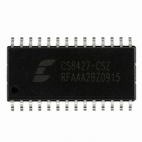
CS8427-CSZ Cirrus Logic Inc, CS8427-CSZ Datasheet - Page 4

CS8427-CSZ
Manufacturer Part Number
CS8427-CSZ
Description
IC TXRX DGTL AUDIO 96KHZ 28SOIC
Manufacturer
Cirrus Logic Inc
Type
Digital Audio Interface Transceiver (DIX)r
Datasheet
1.CS8427-DZZ.pdf
(60 pages)
Specifications of CS8427-CSZ
Applications
Automotive Audio
Mounting Type
Surface Mount
Package / Case
28-SOIC
Audio Control Type
Digital
Control Interface
I2C, Serial
Control / Process Application
AV & DVD Receivers, CD-R, Digital Mixing Consoles
Supply Voltage Range
2.85V To 5.5V
Lead Free Status / RoHS Status
Lead free / RoHS Compliant
For Use With
598-1783 - EVALUATION BOARD FOR CS8427
Lead Free Status / RoHS Status
Lead free / RoHS Compliant, Lead free / RoHS Compliant
Other names
598-1733
Available stocks
Company
Part Number
Manufacturer
Quantity
Price
Company:
Part Number:
CS8427-CSZ
Manufacturer:
CIRRUS
Quantity:
1 370
Part Number:
CS8427-CSZ
Manufacturer:
CIRRUS
Quantity:
20 000
LIST OF FIGURES
LIST OF TABLES
4
Figure 1. Audio Port Master Mode Timing....................................................................................... 8
Figure 2. Audio Port Slave Mode and Data Input Timing ................................................................ 8
Figure 3. SPI Mode timing............................................................................................................... 9
Figure 4. I²C Mode timing.............................................................................................................. 10
Figure 5. Recommended Connection Diagram for Software Mode............................................... 11
Figure 6. CS8427 Internal Block Diagram..................................................................................... 13
Figure 7. Software Mode Audio Data Flow Switching Options...................................................... 19
Figure 8. CS8427 Clock Routing................................................................................................... 20
Figure 9. AES3 Input to Serial Audio Output, Serial Audio Input to AES3 Out ............................. 21
Figure 11. Input Serial Port to AES3 Transmitter without PLL ...................................................... 21
Figure 10. AES3 Input to Serial Audio Output Only ...................................................................... 21
Figure 12. Input Serial Port to AES3 Transmitter with PLL ........................................................... 21
Figure 13. AES3 Receiver Timing for U pin output data ............................................................... 22
Figure 14. AES3 Transmitter Timing for C, U and V pin input data............................................... 22
Figure 15. Serial Audio Input Example Formats............................................................................ 23
Figure 16. Serial Audio Output Example Formats......................................................................... 24
Figure 17. Control Port Timing in SPI Mode.................................................................................. 26
Figure 18. Control Port Timing in I²C Mode................................................................................... 26
Figure 19. Hardware Mode............................................................................................................ 42
Figure 20. Professional Output Circuit .......................................................................................... 50
Figure 21. Consumer Output Circuit.............................................................................................. 50
Figure 22. TTL/CMOS Output Circuit ............................................................................................ 50
Figure 23. Professional Input Circuit ............................................................................................. 51
Figure 24. Transformerless Professional Input Circuit .................................................................. 51
Figure 25. Consumer Input Circuit ................................................................................................ 51
Figure 26. TTL/CMOS Input Circuit............................................................................................... 51
Figure 27. Channel Status Data Buffer Structure.......................................................................... 52
Figure 28. Flowchart for Reading the E Buffer .............................................................................. 53
Figure 29. Flowchart for Writing the E Buffer ................................................................................ 53
Figure 30. PLL Block Diagram ...................................................................................................... 55
Figure 31. Recommended Layout Example .................................................................................. 56
Figure 32. Jitter Tolerance Template ............................................................................................ 58
Figure 33. Revision A .................................................................................................................... 59
Figure 34. Revision A1 .................................................................................................................. 59
Figure 35. Revision A2 using A1 values........................................................................................ 59
Figure 36. Revision A2 using A2* values ...................................................................................... 59
Table 1. Control Register Map Summary ...................................................................................... 27
Table 2. Hardware Mode Start-up Options.................................................................................... 43
Table 3. Serial Audio Output Formats Available in Hardware Mode ............................................. 43
Table 4. Serial Audio Input Formats Available in Hardware Mode................................................ 43
Table 5. Second Line Part Marking ............................................................................................... 57
Table 6. Locking to RXP/RXN - Fs = 8 to 96 kHz ......................................................................... 57
Table 7. Locking to RXP/RXN - Fs = 32 to 96 kHz ....................................................................... 57
Table 8. Locking to the ILRCK Input ............................................................................................. 58
Table 9. Revision History .............................................................................................................. 60
CS8427
DS477F5


