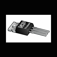
BT151-500R NXP Semiconductors, BT151-500R Datasheet - Page 3

BT151-500R
Manufacturer Part Number
BT151-500R
Description
Planar passivated Silicon Controlled Rectifier (SCR) in a SOT78 plastic package intended for use in applications requiring good bidirectional blocking voltage capability, high surge current capability and high thermal cycling performance
Manufacturer
NXP Semiconductors
Datasheet
1.BT151-500R.pdf
(11 pages)
Available stocks
Company
Part Number
Manufacturer
Quantity
Price
Company:
Part Number:
BT151-500R
Manufacturer:
NSC
Quantity:
101
Company:
Part Number:
BT151-500R
Manufacturer:
NXP
Quantity:
41 413
Company:
Part Number:
BT151-500R
Manufacturer:
PH
Quantity:
750
Company:
Part Number:
BT151-500R
Manufacturer:
NXP
Quantity:
1 200
Part Number:
BT151-500R
Manufacturer:
NXP/恩智浦
Quantity:
20 000
Company:
Part Number:
BT151-500R,127
Manufacturer:
NXP Semiconductors
Quantity:
4 000
Part Number:
BT151-500RT
Manufacturer:
NXP/恩智浦
Quantity:
20 000
NXP Semiconductors
4. Limiting values
Table 4.
In accordance with the Absolute Maximum Rating System (IEC 60134).
BT151-500R_5
Product data sheet
Symbol
V
V
I
I
dI
I
P
T
T
I
I
P
V
T(AV)
T(RMS)
GM
TSM
2
Fig 1.
stg
j
DRM
RRM
GM
G(AV)
RGM
t
T
/dt
I
T(RMS)
(A)
25
20
15
10
5
0
10
duration; maximum values
RMS on-state current as a function of surge
2
Limiting values
rate of rise of on-state
Parameter
repetitive peak off-state
voltage
repetitive peak reverse
voltage
average on-state
current
RMS on-state current
current
peak gate current
peak gate power
storage temperature
junction temperature
non-repetitive peak
on-state current
I2t for fusing
average gate power
peak reverse gate
voltage
10
1
1
surge duration (s)
Conditions
half sine wave; T
half sine wave; T
Figure 2
I
half sine wave; t
half sine wave; t
Figure
t
over any 20 ms period
T
p
= 10 ms; sine-wave pulse
= 20 A; I
001aaa954
4; see
G
10
= 50 mA; dI
Rev. 05 — 2 March 2009
Figure 5
p
p
mb
mb
= 8.3 ms; T
= 10 ms; T
≤ 109 °C; see
≤ 109 °C; see
G
/dt = 50 mA/µs
Fig 2.
I
j(init)
T(RMS)
j(init)
(A)
16
12
= 25 °C; see
8
4
0
= 25 °C
RMS on-state current as a function of mounting
base temperature; maximum values
Figure 3
Figure
50
1; see
0
SCR, 12 A, 15mA, 500 V, SOT78
50
BT151-500R
Min
-
-
-
-
-
-
-
-40
-
-
-
-
-
-
100
© NXP B.V. 2009. All rights reserved.
T
001aaa999
mb
Max
500
500
7.5
12
50
2
5
150
125
132
120
72
0.5
5
( C)
150
Unit
V
V
A
A
A/µs
A
W
°C
°C
A
A
A
W
V
2
3 of 11
s


