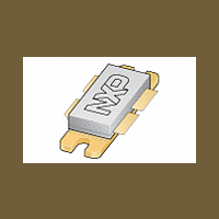
BLF647 NXP Semiconductors, BLF647 Datasheet - Page 2

BLF647
Manufacturer Part Number
BLF647
Description
Silicon N-channel enhancement mode lateral D-MOS push-pull transistor in a SOT540A package with ceramic cap
Manufacturer
NXP Semiconductors
Datasheet
1.BLF647.pdf
(16 pages)
Available stocks
Company
Part Number
Manufacturer
Quantity
Price
Part Number:
BLF647
Manufacturer:
NXP/恩智浦
Quantity:
20 000
Company:
Part Number:
BLF647A
Manufacturer:
GENESYS
Quantity:
1 001
Company:
Part Number:
BLF647A,112
Manufacturer:
HITTITE
Quantity:
1 400
Philips Semiconductors
FEATURES
APPLICATIONS
DESCRIPTION
Silicon N-channel enhancement mode lateral D-MOS
push-pull transistor in a SOT540A package with ceramic
cap. The common source is connected to the mounting
flange.
QUICK REFERENCE DATA
RF performance at T
LIMITING VALUES
In accordance with the Absolute Maximum Rating System (IEC 60134).
2001 Nov 27
CW, class-AB
2-tone,
class-AB
V
V
I
P
T
T
This product is supplied in anti-static packing to prevent damage caused by electrostatic discharge during transport
and handling. For further information, refer to Philips specs.: SNW-EQ-608, SNW-FQ-302A and SNW-FQ-302B.
D
OPERATION
SYMBOL
stg
j
High power gain
Easy power control
Excellent ruggedness
Source on underside eliminates DC isolators, reducing
common mode inductance
Designed for broadband operation (HF to 800 MHz)
Internal input damping for excellent stability over the
whole frequency range.
Communication transmitter applications in the
HF to 800 MHz frequency range.
DS
GS
tot
UHF power LDMOS transistor
MODE OF
drain-source voltage
gate-source voltage
drain current (DC)
total power dissipation
storage temperature
junction temperature
f
1
h
= 600; f
= 25 C in a common source test circuit.
PARAMETER
(MHz)
600
f
2
= 600.1
V
(V)
28
28
DS
T
mb
CAUTION
25 C
2
120 (PEP)
CONDITIONS
PINNING - SOT540A
120
(W)
P
L
PIN
1
2
3
4
5
>14.5
>14.5
Top view
(dB)
Fig.1 Simplified outline.
G
drain 1
drain 2
gate 1
gate 2
source, connected to flange
p
3
1
65
MIN.
DESCRIPTION
2
4
>55
>40
(%)
D
Product specification
MBK777
65
18
290
+150
200
15
MAX.
5
BLF647
(dBc)
V
V
A
W
C
C
d
UNIT
im
26


