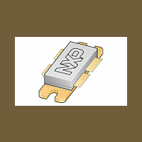
BLF647 NXP Semiconductors, BLF647 Datasheet - Page 5

BLF647
Manufacturer Part Number
BLF647
Description
Silicon N-channel enhancement mode lateral D-MOS push-pull transistor in a SOT540A package with ceramic cap
Manufacturer
NXP Semiconductors
Datasheet
1.BLF647.pdf
(16 pages)
Available stocks
Company
Part Number
Manufacturer
Quantity
Price
Part Number:
BLF647
Manufacturer:
NXP/恩智浦
Quantity:
20 000
Company:
Part Number:
BLF647A
Manufacturer:
GENESYS
Quantity:
1 001
Company:
Part Number:
BLF647A,112
Manufacturer:
HITTITE
Quantity:
1 400
Philips Semiconductors
Application at 600 MHz
2001 Nov 27
handbook, halfpage
handbook, halfpage
UHF power LDMOS transistor
T
2-tone: f
measured in 600 MHz test circuit.
Fig.3
T
measured in 600 MHz test circuit.
Fig.5
h
h
= 25 C; V
(dB)
= 25 C; V
(dB)
G p
G p
20
15
10
20
15
10
5
0
5
0
0
0
1
= 600 MHz ( 6 dB); f
Power gain and drain efficiency as functions
of peak envelope load power; typical
values.
Power gain and drain efficiency as functions
of load power; typical values.
DS
DS
= 28 V; I
= 28 V; I
50
50
G p
G p
DQ
DQ
= 1 A.
= 1 A; CW, class-AB; f = 600 MHz;
2
D
D
= 600.1 MHz ( 6 dB)
100
100
P L (PEP) (W)
150
150
P L (W)
MGW542
MGW540
200
200
80
60
40
20
0
80
60
40
20
0
(%)
(%)
D
D
5
handbook, halfpage
T
2-tone: f
measured in 600 MHz test circuit.
Fig.4
h
(dBc)
d im
= 25 C; V
20
40
60
80
0
0
1
= 600 MHz ( 6 dB); f
Intermodulation distortion as a function of
peak envelope output power; typical values.
DS
= 28 V; I
50
DQ
= 1 A.
2
100
= 600.1 MHz ( 6 dB)
d 3
d 5
P L (PEP) (W)
Product specification
150
MGW541
BLF647
200


