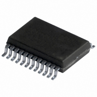
TDA9881TS/V5,118 NXP Semiconductors, TDA9881TS/V5,118 Datasheet - Page 17

TDA9881TS/V5,118
Manufacturer Part Number
TDA9881TS/V5,118
Description
IC IF-PLL DEMOD 24SSOP
Manufacturer
NXP Semiconductors
Type
Demodulatorr
Datasheet
1.TDA9881HNV5118.pdf
(42 pages)
Specifications of TDA9881TS/V5,118
Package / Case
24-SSOP
Applications
Set-Top Boxes
Mounting Type
Surface Mount
Maximum Operating Temperature
+ 70 C
Maximum Power Dissipation
385 mW
Minimum Operating Temperature
- 20 C
Modulation Type
Quadrature
Mounting Style
SMD/SMT
Operating Supply Voltage
5 V
Supply Current
70 A
Lead Free Status / RoHS Status
Lead free / RoHS Compliant
Lead Free Status / RoHS Status
Lead free / RoHS Compliant, Lead free / RoHS Compliant
Other names
935288679118
Philips Semiconductors
Table 10:
V
f
broadband transformer 1 : 1; video modulation DSB; residual carrier for B/G is 10 %; video signal in accordance with “CCIR
line 17 and line 330”; measurements taken in test circuit of
9397 750 13417
Product data sheet
Symbol
CR
Pin VAGC
V
I
I
Tuner AGC; pin TAGC; see
V
V
QV
V
V
I
AFC circuit; pin AFC; see
AFC
Qf
V
V
I
I
SC
o(sink)(max)
o(source)(max)
sink
o(source)
o(sink)
P
QV
G
VAGC
i(VIF)(start1)(rms)
i(VIF)(start2)(rms)
o
sat
sat(ul)
sat(ll)
VIF(a)
= 5 V; T
= 33.4 MHz; PC/SC = 13 dB; f
IF
stps
TOP
stps
TOP
/ T
amb
Characteristics
= 25 C; see
Parameter
control steepness
gain control voltage
range
maximum output sink
current
maximum output source
current
VIF input signal voltage
for minimum starting
point of tuner takeover at
pins VIF1 and VIF2
(RMS value)
VIF input signal voltage
for maximum starting
point of tuner takeover at
pins VIF1 and VIF2
(RMS value)
tuner takeover point
accuracy
takeover point variation
with temperature
permissible output
voltage
saturation voltage
sink current
IF slip by automatic gain
control
AFC control steepness
analog accuracy of AFC
circuit
upper limit saturation
voltage
lower limit saturation
voltage
output source current
output sink current
Table 12
Figure 9
…continued
Figure 6
mod
for input frequencies; B/G standard is used for the specification (f
[14] [15]
= 400 Hz); input level V
to
Figure 8
Conditions
definition:
V
see
I
R
I
R
I
R
I
from external source
I
no tuner gain reduction;
V
maximum tuner gain
reduction; V
tuner gain current from
20 % to 80 %
definition: I
I
f
TAGC
TAGC
TAGC
TAGC
TAGC
AFC
REF
G
VAGC
TAGC
TOP
TOP
TOP
VIF
Rev. 01 — 16 November 2004
Figure 6
= 0 A;
= 4 MHz
= 120 A;
= 22 k
= 120 A;
= 0
= 120 A;
= 10 k
= 120 A
= 450 A
/ V
= 8.8 V
= 2 V to 3 V
VAGC
Alignment-free vision and FM sound IF PLL demodulator
TAGC
AFC
Figure
;
/ f
i(VIF)
= 1 V
VIF
= 10 mV (RMS) (sync level for B/G); IF input from 50
21; unless otherwise specified.
Min
-
0.8
-
-
-
45
7
-
-
-
-
450
3
0.85
V
-
160
160
20
P
0.6
Typ
-
-
-
2
90
17
0.03
-
-
-
600
5
1.05
-
V
0.3
200
200
© Koninklijke Philips Electronics N.V. 2004. All rights reserved.
80
P
0.3
Max
-
3.5
10
10
5
-
43
0.07
8.8
0.5
0.75
750
8
1.25
+20
-
0.6
240
240
PC
TDA9881
= 38.9 MHz;
Unit
dB/V
V
mV
mV
mV
dB/K
V
V
dB
kHz
V
V
A
A
A
A
A/kHz
A
A
17 of 42
via


