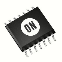
MC74LVX50DTG ON Semiconductor, MC74LVX50DTG Datasheet - Page 6

MC74LVX50DTG
Manufacturer Part Number
MC74LVX50DTG
Description
IC BUFFER HEX NON-INVERT 14TSSOP
Manufacturer
ON Semiconductor
Series
74LVXr
Specifications of MC74LVX50DTG
Logic Type
Buffer/Line Driver, Non-Inverting
Number Of Elements
6
Number Of Bits Per Element
1
Current - Output High, Low
4mA, 4mA
Voltage - Supply
2 V ~ 3.6 V
Operating Temperature
-40°C ~ 85°C
Mounting Type
Surface Mount
Package / Case
14-TSSOP
Circuit Type
Silicon Gate
Current, Supply
20 μA
Function Type
3-Stages
Logic Function
Buffer
Number Of Circuits
Hex
Package Type
TSSOP-14
Special Features
Buffered Output
Temperature, Operating, Range
-40 to +85 °C
Voltage, Supply
2 to 3.6 V
Logic Family
LVX
Number Of Channels Per Chip
5
Polarity
Non-Inverting
Supply Voltage (max)
3.6 V
Supply Voltage (min)
2 V
Maximum Operating Temperature
+ 85 C
Mounting Style
SMD/SMT
High Level Output Current
- 4 mA
Low Level Output Current
4 mA
Maximum Power Dissipation
200 mW
Minimum Operating Temperature
- 40 C
Number Of Lines (input / Output)
6 / 6
Propagation Delay Time
13.6 ns at 2.7 V, 9.7 ns at 3.3 V
Lead Free Status / RoHS Status
Lead free / RoHS Compliant
11. A
0.50 mm max. The component cannot rotate more than 10 within the determined cavity
0
10
, B
BENDING RADIUS
0
, and K
INCLUDING DRAFT AND RADII
FOR MACHINE REFERENCE
CONCENTRIC AROUND B
MAXIMUM COMPONENT ROTATION
0
are determined by component size. The clearance between the components and the cavity must be within 0.05 mm min to
ONLY
B
1
TYPICAL
COMPONENT CAVITY
CENTER LINE
TYPICAL
COMPONENT
CENTER LINE
R MIN.
TAPE AND COMPONENTS
SHALL PASS AROUND RADIUS “R”
WITHOUT DAMAGE
NOTE
SEE
K
t
11
0
K
COVER
0
TAPE
TOP
Figure 6. Carrier Tape Specifications
ALLOWABLE CAMBER TO BE 1 mm/100 mm NONACCUMULATIVE OVER 250
USER DIRECTION OF FEED
D
http://onsemi.com
MC74LVX50
EMBOSSMENT
+
6
B
A
0
P
0
100 mm
(3.937”)
SEE NOTE 11
P
EMBOSSED
CARRIER
2
P
+
0
1 mm MAX
CAMBER (TOP VIEW)
OF CAVITY
10 PITCHES
CUMULATIVE
TOLERANCE ON
TAPE
( 0.008”)
CENTER
0.2 mm
+
LINES
(0.039”) MAX
*TOP COVER
TAPE THICKNESS (t
0.10 mm
(0.004”) MAX.
E
F
1 mm
W
D
FOR COMPONENTS
2.0 mm
AND LARGER
1
EMBOSSMENT
TAPE
250 mm
(9.843”)
1.2 mm
1
)
mm


