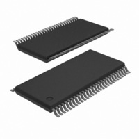
74ALVCH16601DGG,11 NXP Semiconductors, 74ALVCH16601DGG,11 Datasheet - Page 10

74ALVCH16601DGG,11
Manufacturer Part Number
74ALVCH16601DGG,11
Description
IC UNIV BUS TXRX 18BIT 56TSSOP
Manufacturer
NXP Semiconductors
Series
74ALVCHr
Datasheet
1.74ALVCH16601DGG11.pdf
(12 pages)
Specifications of 74ALVCH16601DGG,11
Logic Type
Universal Bus Transceiver
Package / Case
56-TSSOP
Number Of Circuits
18-Bit
Current - Output High, Low
24mA, 24mA
Voltage - Supply
2.3 V ~ 3.6 V
Operating Temperature
-40°C ~ 85°C
Mounting Type
Surface Mount
Logic Family
ALVC
Number Of Channels Per Chip
18
Input Level
LVTTL
Output Level
LVTTL
Output Type
3-State
High Level Output Current
- 24 mA
Low Level Output Current
24 mA
Propagation Delay Time
3.1 ns
Supply Voltage (max)
3.6 V
Supply Voltage (min)
2.3 V
Maximum Operating Temperature
+ 85 C
Function
Universal Bus Transceiver
Input Bias Current (max)
40 uA
Minimum Operating Temperature
- 40 C
Mounting Style
SMD/SMT
Polarity
Non-Inverting
Lead Free Status / RoHS Status
Lead free / RoHS Compliant
Lead Free Status / RoHS Status
Lead free / RoHS Compliant, Lead free / RoHS Compliant
Other names
74ALVCH16601DG
74ALVCH16601DG
935262546112
74ALVCH16601DG
935262546112
1. V
2. V
3. V
4. V
5. V
1. V
2. V
3. V
4. V
5. V
Philips Semiconductors
AC WAVEFORMS
V
V
1998 Sep 24
Waveform 2. Latch enable input (LE
CC
CC
Waveform 1. Input (An, Bn) to output (Bn, An) propagation
18-bit universal bus transceiver (3-State)
OUTPUT
LOW-to-OFF
OFF-to-LOW
OUTPUT
HIGH-to-OFF
OFF-to-HIGH
input (CP
the output load.
the output load.
OE
= 2.3 TO 2.7 V RANGE
= 3.0 TO 3.6 V RANGE AND V
M
X
Y
I
OL
M
X
Y
I
OL
GND
V
V
V
GND
XX
V
= V
= 2.7 V
OL
OH
CC
= V
= V
= V
= V
= 0.5 V
= 1.5 V
I
LE
INPUT
CP
INPUT
An, Bn
OUTPUT
and V
and V
INPUT
V
An, Bn
INPUT
GND
V
Bn, An
OUTPUT
V
Waveform 3. 3-State enable and disable times
CC
V
V
I
OH
OL
XX
XX
OL
OH
OL
OH
OH
OL
GND
V
AB
+ 0.15V
+ 0.3V
– 0.15V
– 0.3V
I
OH
OH
, CP
are the typical output voltage drop that occur with
are the typical output voltage drop that occur with
outputs
en-
abled
V
M
BA
V
t
PLZ
M
t
V
PHZ
t
) to output propagation delays and their
PHL
M
t
PHL
t
W
pulse width
V
V
delays
1/f
X
V
M
Y
V
max
M
CC
outputs
dis-
abled
= 2.7 V
AB
, LE
t
PZL
t
PZH
t
PLH
BA
t
PLH
SW00063
) and clock pulse
V
M
V
M
SW00127
outputs
en-
abled
SW00134
10
TEST CIRCUIT
Waveform 4. Data set-up and hold times for the An and Bn
CP
An, Bn
INPUT
INPUT
NOTE: The unshaded areas indicate when the input is permitted
DEFINITIONS
R
C
R
GENERATOR
SWITCH POSITION
GND
GND
XX
t
t
t
PHZ
L
L
T
É É É
É É É
É É É
PLH
PLZ
TEST
V
V
PULSE
, LE
= Load resistor
= Load capacitance includes jig and probe capacitance
= Termination resistance should be equal to Z
I
I
inputs to the LE
of pulse generators.
/t
/t
/t
XX
to change for predictable output performance.
PHL
PZL
PZH
Load circuitry for switching times
Test Circuit for 3-State Outputs
SWITCH
2<V
V
t
Open
SU
GND
V
M
IN
CC
R
V
T
AB
t
M
h
É É É É É É É
É É É É É É É
É É É É É É É
, LE
D.U.T.
V
BA
CC
, CP
2.7 – 3.6V
74ALVCH16601
t 2.7V
AB
V
V
OUT
CC
and CP
C
L
t
SU
Product specification
2.7V
BA
V
V
CC
IN
OUT
inputs
t
É É É
É É É
É É É
S
h
1
R
R
L
L
SW00128
=500
=500
2<V
GND
Open
SW00047
CC


