M27C1001-12F1 STMicroelectronics, M27C1001-12F1 Datasheet - Page 5
M27C1001-12F1
Manufacturer Part Number
M27C1001-12F1
Description
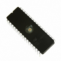
IC EPROM 1MBIT 120NS 32CDIP
Manufacturer
STMicroelectronics
Datasheets
1.M27C1001-12C6.pdf
(24 pages)
2.M27C1001-15F1.pdf
(10 pages)
3.M27C1001-12F1.pdf
(17 pages)
Specifications of M27C1001-12F1
Format - Memory
EPROMs
Memory Type
UV EPROM
Memory Size
1M (128K x 8)
Speed
120ns
Interface
Parallel
Voltage - Supply
4.5 V ~ 5.5 V
Operating Temperature
0°C ~ 70°C
Package / Case
32-CDIP (0.600", 15.24mm) Window
Capacitance, Input
6 pF
Capacitance, Output
12 pF
Current, Input, Leakage
±10 μA (Read)
Current, Operating
30 mA (Read)
Current, Output, Leakage
±10 μA (Read)
Current, Supply
30 mA
Density
1M
Organization
128K×8
Package Type
FDIP32W
Temperature, Operating
0 to +70 °C
Temperature, Operating, Maximum
70 °C
Temperature, Operating, Minimum
0 °C
Time, Access
120 ns
Time, Fall
≤20 ns
Time, Programmable
100 μs
Time, Rise
≤20 ns
Voltage, Input, High
6 V (Read)
Voltage, Input, High Level
2 V (Min.)
Voltage, Input, Low
0.8 V (Read)
Voltage, Input, Low Level
-0.3 V (Max.)
Voltage, Output, High
4.3 V (Read)
Voltage, Output, Low
0.4 V (Read)
Voltage, Programmable
11.5 V (Min.)
Voltage, Supply
5 V
Memory Configuration
128K X 8
Access Time
120ns
Supply Voltage Range
4.5V To 5.5V
Memory Case Style
DIP
No. Of Pins
32
Rohs Compliant
Yes
Lead Free Status / RoHS Status
Lead free / RoHS Compliant
Other names
497-1631-5
Available stocks
Company
Part Number
Manufacturer
Quantity
Price
Company:

Part Number:
M27C1001-12F1
Manufacturer:
ST
Quantity:
651
Part Number:
M27C1001-12F1
Manufacturer:
ST
Quantity:
20 000
Part Number:
M27C1001-12F1L
Manufacturer:
ST
Quantity:
20 000


Table 7. Read Mode DC Characteristics
(TA = 0 to 70°C, –40 to 85°C or –40 to 125°C; V
Note: 1. V
Table 8A. Read Mode AC Characteristics
(TA = 0 to 70°C, –40 to 85°C or –40 to 125°C; V
Note: 1. V
Two Line Output Control
Because EPROMs are usually used in larger
memory arrays, this product features a 2 line con-
trol function which accommodates the use of mul-
tiple memory connection. The two line control
function allows:
a. the lowest possible memory power dissipation,
b. complete assurance that output bus contention
t
t
Symbol
Symbol
EHQZ
GHQZ
V
will not occur.
t
t
t
t
I
I
V
V
AVQV
ELQV
GLQV
AXQX
I
I
CC1
CC2
I
V
IH
I
LO
CC
PP
OH
LI
OL
2. Maximum DC voltage on Output is V
2. Sampled only, not 100% tested.
3. Speed obtained with High Speed AC measurement conditions.
IL
(2)
(2)
(2)
CC
CC
must be applied simultaneously with or before V
must be applied simultaneously with or before V
Input Leakage Current
Output Leakage Current
Supply Current
Supply Current (Standby) TTL
Supply Current (Standby) CMOS
Program Current
Input Low Voltage
Input High Voltage
Output Low Voltage
Output High Voltage TTL
Output High Voltage CMOS
t
Alt
ACC
t
t
t
t
t
OH
CE
OE
DF
DF
Address Valid to
Output Valid
Chip Enable Low to
Output Valid
Output Enable Low
to Output Valid
Chip Enable High to
Output Hi-Z
Output Enable High
to Output Hi-Z
Address Transition
to Output Transition
Parameter
Parameter
CC
+0.5V.
Test Condition
E = V
E = V
G = V
G = V
(1)
E = V
E = V
IL
IL
(1)
, G = V
, G = V
PP
PP
IL
IL
IL
IL
CC
CC
I
OUT
and removed simultaneously or after V
and removed simultaneously or after V
0V
E = V
Test Condition
IL
IL
= 5V ± 5% or 5V ± 10%; V
E > V
= 5V ± 5% or 5V ± 10%; V
0V
I
I
OH
OH
I
= 0mA, f = 5MHz
OL
V
For the most efficient use of these two control
lines, E should be decoded and used as the prima-
ry device selecting function, while G should be
made a common connection to all devices in the
array and connected to the READ line from the
system control bus. This ensures that all deselect-
ed memory devices are in their low power standby
mode and that the output pins are only active
when data is required from a particular memory
device.
E = V
PP
Min Max Min Max Min Max Min Max
V
= –400µA
= –100µA
IL
0
0
0
V
= 2.1mA
CC
OUT
-35
, G = V
IN
= V
– 0.2V
IH
(3)
CC
35
35
25
25
25
V
V
CC
CC
IL
,
0
0
0
-45
M27C1001
25
25
45
45
25
V
CC
–0.3
PP
Min
PP
2.4
PP
PP
0
0
0
– 0.7V
2
.
.
-60
= V
= V
60
60
30
30
30
CC
CC
)
)
V
CC
Max
±10
±10
100
0
0
0
0.8
0.4
30
10
1
-70
+ 1
M27C1001
70
70
35
30
30
Unit
mA
mA
µA
µA
µA
µA
Unit
V
V
V
V
V
ns
ns
ns
ns
ns
ns
5/17
Related parts for M27C1001-12F1
Image
Part Number
Description
Manufacturer
Datasheet
Request
R

Part Number:
Description:
Manufacturer:
STMicroelectronics
Datasheet:

Part Number:
Description:
IC OTP 1MBIT 120NS 32PLCC
Manufacturer:
STMicroelectronics
Datasheet:

Part Number:
Description:
IC EPROM 1MBIT 150NS 32CDIP
Manufacturer:
STMicroelectronics
Datasheet:

Part Number:
Description:
IC EPROM 1MBIT 70NS 32CDIP
Manufacturer:
STMicroelectronics
Datasheet:
Part Number:
Description:
IC OTP 1MBIT 100NS 32PLCC
Manufacturer:
STMicroelectronics
Datasheet:
Part Number:
Description:
IC OTP 1MBIT 70NS 32PLCC
Manufacturer:
STMicroelectronics
Datasheet:

Part Number:
Description:
IC OTP 1MBIT 70NS 32DIP
Manufacturer:
STMicroelectronics
Datasheet:
Part Number:
Description:
IC OTP 1MBIT 100NS 32DIP
Manufacturer:
STMicroelectronics
Datasheet:
Part Number:
Description:
IC EPROM 1MBIT 45NS 32CDIP
Manufacturer:
STMicroelectronics
Datasheet:

Part Number:
Description:
IC EPROM 1MBIT 100NS 32CDIP
Manufacturer:
STMicroelectronics
Datasheet:

Part Number:
Description:
IC EPROM 1MBIT 120NS 32CDIP
Manufacturer:
STMicroelectronics
Datasheet:
Part Number:
Description:
IC OTP 1MBIT 100NS 32PLCC
Manufacturer:
STMicroelectronics
Datasheet:
Part Number:
Description:
IC OTP 1MBIT 120NS 32DIP
Manufacturer:
STMicroelectronics
Datasheet: