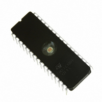
M27C1001-12F1 STMicroelectronics, M27C1001-12F1 Datasheet - Page 8

M27C1001-12F1
Manufacturer Part Number
M27C1001-12F1
Description
IC EPROM 1MBIT 120NS 32CDIP
Manufacturer
STMicroelectronics
Datasheets
1.M27C1001-12C6.pdf
(24 pages)
2.M27C1001-15F1.pdf
(10 pages)
3.M27C1001-12F1.pdf
(17 pages)
Specifications of M27C1001-12F1
Format - Memory
EPROMs
Memory Type
UV EPROM
Memory Size
1M (128K x 8)
Speed
120ns
Interface
Parallel
Voltage - Supply
4.5 V ~ 5.5 V
Operating Temperature
0°C ~ 70°C
Package / Case
32-CDIP (0.600", 15.24mm) Window
Capacitance, Input
6 pF
Capacitance, Output
12 pF
Current, Input, Leakage
±10 μA (Read)
Current, Operating
30 mA (Read)
Current, Output, Leakage
±10 μA (Read)
Current, Supply
30 mA
Density
1M
Organization
128K×8
Package Type
FDIP32W
Temperature, Operating
0 to +70 °C
Temperature, Operating, Maximum
70 °C
Temperature, Operating, Minimum
0 °C
Time, Access
120 ns
Time, Fall
≤20 ns
Time, Programmable
100 μs
Time, Rise
≤20 ns
Voltage, Input, High
6 V (Read)
Voltage, Input, High Level
2 V (Min.)
Voltage, Input, Low
0.8 V (Read)
Voltage, Input, Low Level
-0.3 V (Max.)
Voltage, Output, High
4.3 V (Read)
Voltage, Output, Low
0.4 V (Read)
Voltage, Programmable
11.5 V (Min.)
Voltage, Supply
5 V
Memory Configuration
128K X 8
Access Time
120ns
Supply Voltage Range
4.5V To 5.5V
Memory Case Style
DIP
No. Of Pins
32
Rohs Compliant
Yes
Lead Free Status / RoHS Status
Lead free / RoHS Compliant
Other names
497-1631-5
Available stocks
Company
Part Number
Manufacturer
Quantity
Price
Company:
Part Number:
M27C1001-12F1
Manufacturer:
ST
Quantity:
651
Part Number:
M27C1001-12F1
Manufacturer:
ST
Quantity:
20 000
Part Number:
M27C1001-12F1L
Manufacturer:
ST
Quantity:
20 000
M27C1001
Figure 6. Programming and Verify Modes AC Waveforms
Figure 7. Programming Flowchart
8/17
YES
NO
FAIL
= 25
++n
V CC
A0-A16
Q0-Q7
V PP
E
P
G
V CC = 6.25V, V PP = 12.75V
CHECK ALL BYTES
NO
2nd: V CC = 4.2V
P = 100 s Pulse
1st: V CC = 6V
VERIFY
n = 0
Addr
Last
YES
YES
tVPHPL
tVCHPL
NO
tAVPL
tELPL
tQVPL
tPLPH
++ Addr
DATA IN
PROGRAM
AI00715C
VALID
tPHQX
PRESTO II Programming Algorithm
PRESTO II Programming Algorithm allows the
whole array to be programmed, with a guaranteed
margin, in a typical time of 13 seconds. Program-
ming with PRESTO II involves in applying a se-
quence of 100µs program pulses to each byte until
a correct verify occurs (see Figure 7). During pro-
gramming and verify operation, a MARGIN MODE
circuit is automatically activated in order to guar-
antee that each cell is programmed with enough
margin. No overprogram pulse is applied since the
verify in MARGIN MODE provides necessary mar-
gin to each programmed cell.
Program Inhibit
Programming of multiple M27C1001s in parallel
with different data is also easily accomplished. Ex-
cept for E, all like inputs including G of the parallel
M27C1001 may be common. A TTL low level
pulse applied to a M27C1001's P input, with E low
and V
A high level E input inhibits the other M27C1001s
from being programmed.
Program Verify
A verify (read) should be performed on the pro-
grammed bits to determine that they were correct-
ly programmed. The verify is accomplished with E
and G at V
6.25V.
tQXGL
PP
VERIFY
tGLQV
DATA OUT
at 12.75V, will program that M27C1001.
IL
, P at V
IH
, V
PP
tGHQZ
tGHAX
at 12.75V and V
AI00714
CC
at


