DS2433+ Maxim Integrated Products, DS2433+ Datasheet - Page 21
DS2433+
Manufacturer Part Number
DS2433+
Description
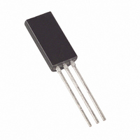
IC EEPROM 4KBIT TO92-3
Manufacturer
Maxim Integrated Products
Datasheet
1.DS2433.pdf
(23 pages)
Specifications of DS2433+
Format - Memory
EEPROMs - Serial
Memory Type
EEPROM
Memory Size
4K (256 x 16)
Interface
1-Wire Serial
Operating Temperature
-40°C ~ 85°C
Package / Case
TO-92-3 (Long Body), TO-226
Organization
4 K x 1
Interface Type
1-Wire
Supply Voltage (max)
6 V
Supply Voltage (min)
2.8 V
Maximum Operating Current
500 uA
Maximum Operating Temperature
+ 85 C
Mounting Style
Through Hole
Minimum Operating Temperature
- 40 C
Lead Free Status / RoHS Status
Lead free / RoHS Compliant
Voltage - Supply
-
Speed
-
Lead Free Status / Rohs Status
Lead free / RoHS Compliant


AC ELECTRICAL CHARACTERISTICS—OVERDRIVE SPEED
NOTES:
1) V
2) All voltages are referenced to ground.
3) V
4) Input load is to ground.
5) The Copy Scratchpad takes 5ms maximum during which the voltage on the 1-Wire bus must not fall
6) Capacitance on the data pin could be 800pF when power is first applied. If a 5kresistor is used to
7) During the execution of the Copy Scratchpad command the DS2433 automatically erases the memory
8) The duration of the low pulse sent by the master should be a minimum of 1μs with a maximum value
9) The optimal sampling point for the master is as close as possible to the end time of the t
10) Read data setup time refers to the time the host must pull the 1-Wire bus low to read a bit. Data is
11) An additional reset or communication sequence cannot begin until the reset high time has expired.
12) The reset low time (t
Time Slot
Write 1 Low Time
Write 0 Low Time
Read Low Time
Read Data Valid
Release Time
Read Data Setup
Recovery Time
Reset Time High
Reset Time Low
Presence Detect High
Presence Detect Low
below 2.8V.
pull up the data line to V
normal communications.
locations to be written to. No extra steps need to be taken by the bus master.
as short as possible to allow time for the pullup resistor to recover the line to a high level before the
1-Wire device samples in the case of a write-one time or before the master samples in the case of a
read-one time.
without exceeding t
the pullup resistor to recover to a high level. For a read-zero time slot, it ensures that a read will occur
before the fastest device(s) release the line.
guaranteed to be valid within 1 s of this falling edge.
otherwise, it could mask or conceal interrupt pulses.
PUP
IH
is a function of the external pullup resistor and V
PARAMETER
= external pullup voltage. See Figure 8.
RDV
RSTL
. For the case of a read-one time slot, this maximizes the amount of time for
PUP
) should be restricted to a maximum of 960s, to allow interrupt signaling,
, 5s after power has been applied the parasite capacitance will not affect
SYMBOL
t
t
RELEASE
t
t
PDHIGH
t
t
PDLOW
t
t
t
LOWR
t
LOW1
LOW0
t
RSTH
SLOT
RSTL
RDV
t
REC
SU
21 of 23
MIN
48
48
6
1
6
1
0
1
2
8
PUP
.
TYP
1.5
2
MAX
16
16
80
24
2
2
4
1
6
(T
A
UNITS
= -40C to +85C.)
s
s
s
s
s
s
s
s
s
s
s
s
RDV
NOTES
10
11
8
8
9
period
Related parts for DS2433+
Image
Part Number
Description
Manufacturer
Datasheet
Request
R

Part Number:
Description:
MAX7528KCWPMaxim Integrated Products [CMOS Dual 8-Bit Buffered Multiplying DACs]
Manufacturer:
Maxim Integrated Products
Datasheet:
Part Number:
Description:
Single +5V, fully integrated, 1.25Gbps laser diode driver.
Manufacturer:
Maxim Integrated Products
Datasheet:
Part Number:
Description:
Single +5V, fully integrated, 155Mbps laser diode driver.
Manufacturer:
Maxim Integrated Products
Datasheet:
Part Number:
Description:
VRD11/VRD10, K8 Rev F 2/3/4-Phase PWM Controllers with Integrated Dual MOSFET Drivers
Manufacturer:
Maxim Integrated Products
Datasheet:
Part Number:
Description:
Highly Integrated Level 2 SMBus Battery Chargers
Manufacturer:
Maxim Integrated Products
Datasheet:
Part Number:
Description:
Current Monitor and Accumulator with Integrated Sense Resistor; ; Temperature Range: -40°C to +85°C
Manufacturer:
Maxim Integrated Products
Part Number:
Description:
TSSOP 14/A�/RS-485 Transceivers with Integrated 100O/120O Termination Resis
Manufacturer:
Maxim Integrated Products
Part Number:
Description:
TSSOP 14/A�/RS-485 Transceivers with Integrated 100O/120O Termination Resis
Manufacturer:
Maxim Integrated Products
Part Number:
Description:
QFN 16/A�/AC-DC and DC-DC Peak-Current-Mode Converters with Integrated Step
Manufacturer:
Maxim Integrated Products
Part Number:
Description:
TDFN/A/65V, 1A, 600KHZ, SYNCHRONOUS STEP-DOWN REGULATOR WITH INTEGRATED SWI
Manufacturer:
Maxim Integrated Products
Part Number:
Description:
Integrated Temperature Controller f
Manufacturer:
Maxim Integrated Products
Part Number:
Description:
SOT23-6/I�/45MHz to 650MHz, Integrated IF VCOs with Differential Output
Manufacturer:
Maxim Integrated Products
Part Number:
Description:
SOT23-6/I�/45MHz to 650MHz, Integrated IF VCOs with Differential Output
Manufacturer:
Maxim Integrated Products
Part Number:
Description:
EVALUATION KIT/2.4GHZ TO 2.5GHZ 802.11G/B RF TRANSCEIVER WITH INTEGRATED PA
Manufacturer:
Maxim Integrated Products
Part Number:
Description:
QFN/E/DUAL PCIE/SATA HIGH SPEED SWITCH WITH INTEGRATED BIAS RESISTOR
Manufacturer:
Maxim Integrated Products
Datasheet: