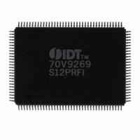
IDT70V9269S12PRFI IDT, Integrated Device Technology Inc, IDT70V9269S12PRFI Datasheet - Page 8

IDT70V9269S12PRFI
Manufacturer Part Number
IDT70V9269S12PRFI
Description
IC SRAM 256KBIT 12NS 128TQFP
Manufacturer
IDT, Integrated Device Technology Inc
Datasheet
1.IDT70V9269S12PRFI.pdf
(19 pages)
Specifications of IDT70V9269S12PRFI
Format - Memory
RAM
Memory Type
SRAM - Dual Port, Synchronous
Memory Size
256K (16K x 16)
Speed
12ns
Interface
Parallel
Voltage - Supply
3 V ~ 3.6 V
Operating Temperature
-40°C ~ 85°C
Package / Case
128-TQFP, 128-VQFP
Lead Free Status / RoHS Status
Contains lead / RoHS non-compliant
Other names
70V9269S12PRFI
800-1399
800-1399
Available stocks
Company
Part Number
Manufacturer
Quantity
Price
Company:
Part Number:
IDT70V9269S12PRFI
Manufacturer:
IDT
Quantity:
881
Company:
Part Number:
IDT70V9269S12PRFI
Manufacturer:
IDT, Integrated Device Technology Inc
Quantity:
10 000
AC Electrical Characteristics Over the Operating Temperature Range
(Read and Write Cycle Timing)
NOTES:
1. Transition is measured 0mV from Low or High-impedance voltage with the Output Test Load (Figure 2). This parameter is guaranteed by device characteriza-
2. The Pipelined output parameters (t
3. All input signals are synchronous with respect to the clock except for the asynchronous Output Enable (OE) and FT/PIPE. FT/PIPE should be treated as a
4. 'X' in part number indicates power rating (S or L).
Port-to-Port Delay
t
t
t
t
t
t
t
t
t
t
t
t
t
t
t
t
t
t
t
t
t
t
t
t
t
t
t
t
t
t
t
t
CYC1
CYC2
CH1
CL1
CH2
CL2
R
F
SA
HA
SC
HC
SW
HW
SD
HD
SAD
HAD
SCN
HCN
SRST
HRST
OE
OLZ
OHZ
CD1
CD2
DC
CKHZ
CKLZ
CWDD
CCS
IDT70V9279/69S/L
High-Speed 32/16K x 16 Dual-Port Synchronous Static RAM
Symbol
tion, but is not production tested.
FT/PIPE = V
DC signal, i.e. steady state during operation.
Clock Cycle Time (Flow-Through)
Clock Cycle Time (Pipelined)
Clock High Time (Flow-Through)
Clock Low Time (Flow-Through)
Clock High Time (Pipelined)
Clock Low Time (Pipelined)
Clock Rise Time
Clock Fall Time
Chip Enable Setup Time
Chip Enable Hold Time
R/W Setup Time
R/W Hold Time
Input Data Setup Time
Input Data Hold Time
Output Enable to Data Valid
Output Enable to Output Low-Z
Output Enable to Output High-Z
Clock to Data Valid (Flow-Through)
Clock to Data Valid (Pipelined)
Data Output Hold After Clock High
Clock High to Output High-Z
Clock High to Output Low-Z
Clock-to-Clock Setup Time
IL
Address Setup Time
Address Hold Time
ADS Setup Time
ADS Hold Time
CNTEN Setup Time
CNTEN Hold Time
CNTRST Setup Time
CNTRST Hold Time
Write Port Clock High to Read Data Delay
for that port.
CYC2
, t
(1)
(2)
(1)
(2)
CD2
(2)
(1)
(2)
(1)
(2)
(2)
) apply to either or both left and right ports when FT/PIPE = V
(2)
Parameter
(2)
(3,4)
(V
6.42
DD
8
= 3.3V ± 0.3V, T
Min.
70V9279/69X6
6.5
6.5
____
____
3.5
3.5
3.5
3.5
3.5
3.5
3.5
____
____
____
____
____
19
10
Com'l Only
4
4
0
0
0
0
0
0
0
2
2
2
2
1
Industrial and Commercial Temperature Ranges
Max.
____
____
____
____
____
____
____
____
____
____
____
____
____
____
____
____
____
____
____
____
6.5
____
6.5
____
____
15
24
3
3
7
9
9
IH
. Flow-through parameters (t
A
= 0°C to +70°C)
Min.
70V9279/69X7
7.5
7.5
____
____
____
____
____
____
____
22
12
5
5
4
0
4
0
4
0
4
0
4
0
4
0
4
0
2
2
2
2
1
Com'l
& Ind
Max.
7.5
7.5
____
____
____
____
____
____
____
____
____
____
____
____
____
____
____
____
____
____
____
____
____
____
____
28
18
10
3
3
7
9
Min.
70V9279/69X9
____
____
____
____
____
____
____
25
15
12
12
Com'l Only
6
6
4
4
4
4
4
4
4
2
2
2
2
1
1
1
1
1
1
1
1
CYC1
, t
CD1
Max.
____
____
____
____
____
____
____
____
____
____
____
____
____
____
____
____
____
____
____
____
____
____
____
20
35
15
3
3
9
7
9
9
) apply when
3743 tbl 11a
Unit
ns
ns
ns
ns
ns
ns
ns
ns
ns
ns
ns
ns
ns
ns
ns
ns
ns
ns
ns
ns
ns
ns
ns
ns
ns
ns
ns
ns
ns
ns
ns
ns


