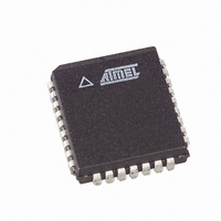
AT49LH00B4-33JX Atmel, AT49LH00B4-33JX Datasheet - Page 21

AT49LH00B4-33JX
Manufacturer Part Number
AT49LH00B4-33JX
Description
IC FLASH 4MBIT 33MHZ 32PLCC
Manufacturer
Atmel
Datasheet
1.AT49LH00B4-33JC.pdf
(41 pages)
Specifications of AT49LH00B4-33JX
Format - Memory
FLASH
Memory Type
FLASH
Memory Size
4M (512K x 8)
Speed
33MHz
Interface
Parallel
Voltage - Supply
3 V ~ 3.6 V
Operating Temperature
0°C ~ 85°C
Package / Case
32-PLCC
Lead Free Status / RoHS Status
Lead free / RoHS Compliant
Available stocks
Company
Part Number
Manufacturer
Quantity
Price
Part Number:
AT49LH00B4-33JX
Manufacturer:
AT
Quantity:
20 000
11.2.1
11.2.2
11.2.3
3379C–FLASH–3/05
Read Lock
Write Lock
Lock Down
Table 11-2.
The default read status of all sectors upon power-up is read-unlocked. When a sector’s Read-
Lock bit is set (1 state), data cannot be read from that sector. An attempted read from a read-
locked sector will result in data 00H being read (note that a read failure is not reflected in the
Status Register). The read lock status can be unlocked by clearing (0 state) the Read-Lock bit,
provided that the Lock-Down bit has not been set. The current read lock status of a particular
sector can be determined by reading the corresponding Read-Lock bit.
The default write status of all sectors upon power-up is write-locked (1 state). Any program or
erase operations attempted on a locked sector will return an error in the Status Register (indicat-
ing sector lock). The status of the locked sector can be changed to unlocked (0 state) by clearing
the Write-Lock bit, provided that the Lock-Down bit is not set. The current write lock status of a
particular sector can be determined by reading the corresponding Write-Lock bit.
The Write-Lock bit must be set to the desired protection state prior to starting a program or erase
operation because it is sampled at the beginning of the operation. Changing the state of the
Write-Lock bit during a program or erase operation may cause unpredictable results. The new
lock status will take place after the program or erase operation completes.
The write lock functions independently of the hardware write protect pins, TBL and WP. When
active, these pins take precedence over the register-based write lock function. Changing the
state of the TBL and WP pins will not affect the state of the Write-Lock bits. Reading the Sector
Locking Registers will not read the state of the TBL or WP pins.
When in the FWH/LPC interface mode, the default lock down status of all sectors upon power-
up is not-locked-down (0 state). The Lock-Down bit for any sector may be set (1 state), but only
once, as future attempted changes to that Sector Locking Register will be ignored. Once a sec-
tor’s Lock-Down bit is set, the Read-Lock and Write-Lock bits for that sector can no longer be
modified, and the sector is locked down in its current state of read and write accessibility. The
Register
S10_LK
S9_LK
S8_LK
S7_LK
S6_LK
S5_LK
S4_LK
S3_LK
S2_LK
S1_LK
S0_LK
Name
Sector Locking Registers
Associated
Sector
10
9
8
7
6
5
4
3
2
1
0
Sector Size
(Bytes)
64K
64K
64K
64K
64K
64K
64K
32K
16K
8K
8K
FWH MODE
FFBF0002H
FFBE0002H
FFBD0002H
FFBC0002H
FFBB0002H
FFBA0002H
FFB90002H
FFB88002H
FFB84002H
FFB82002H
FFB80002H
Register Memory Address
FF7E0002H
FF7D0002H
FF7C0002H
FF7B0002H
FF7A0002H
LPC MODE
FF7F0002H
FF790002H
FF788002H
FF784002H
FF782002H
FF780002H
AT49LH00B4
Default Value
01H
01H
01H
01H
01H
01H
01H
01H
01H
01H
01H
21


