AT45DB041D-MU-2.5 Atmel, AT45DB041D-MU-2.5 Datasheet - Page 8
AT45DB041D-MU-2.5
Manufacturer Part Number
AT45DB041D-MU-2.5
Description
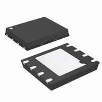
IC FLASH 4MBIT 66MHZ 8MLF
Manufacturer
Atmel
Datasheet
1.AT45DB041D-MU.pdf
(55 pages)
Specifications of AT45DB041D-MU-2.5
Format - Memory
FLASH
Memory Type
DataFLASH
Memory Size
4M (2048 pages x 264 bytes)
Speed
66MHz
Interface
SPI, RapidS
Voltage - Supply
2.5 V ~ 3.6 V
Operating Temperature
-40°C ~ 85°C
Package / Case
8-VFQFN, 8-VFQFPN
Architecture
Sectored
Interface Type
SPI
Supply Voltage (max)
3.6 V
Supply Voltage (min)
2.5 V
Maximum Operating Current
15 mA
Mounting Style
SMD/SMT
Organization
64 KB x 8
Density
4Mb
Access Time (max)
8ns
Boot Type
Not Required
Address Bus
1b
Operating Supply Voltage (typ)
3/3.3V
Operating Temp Range
-40C to 85C
Package Type
MLF
Program/erase Volt (typ)
2.5 to 3.6V
Sync/async
Synchronous
Operating Temperature Classification
Industrial
Operating Supply Voltage (min)
2.5V
Operating Supply Voltage (max)
3.6V
Supply Current
15mA
Mounting
Surface Mount
Pin Count
8
Lead Free Status / RoHS Status
Lead free / RoHS Compliant
Available stocks
Company
Part Number
Manufacturer
Quantity
Price
Company:

Part Number:
AT45DB041D-MU-2.5
Manufacturer:
ATMEL
Quantity:
1 600
Part Number:
AT45DB041D-MU-2.5
Manufacturer:
ATMEL/爱特梅尔
Quantity:
20 000


7.3
7.4
7.5
8
Buffer to Main Memory Page Program without Built-in Erase
Page Erase
Block Erase
AT45DB041D
11 page address bits (A18 - A8) that specify the page in the main memory to be written and
8 don’t care bits. When a low-to-high transition occurs on the CS pin, the part will first erase the
selected page in main memory (the erased state is a logic 1) and then program the data stored
in the buffer into the specified page in main memory. Both the erase and the programming of the
page are internally self-timed and should take place in a maximum time of t
the status register will indicate that the part is busy.
A previously-erased page within main memory can be programmed with the contents of either
buffer 1 or buffer 2. A 1-byte opcode, 88H for buffer 1 or 89H for buffer 2, must be clocked into
the device. For the DataFlash standard page size (264 bytes), the opcode must be followed by
three address bytes consist of 4 don’t care bits, 11 page address bits (PA10 - PA0) that specify
the page in the main memory to be written and 9 don’t care bits. To perform a buffer to main
memory page program without built-in erase for the binary page size (256 bytes), the opcode
88H for buffer 1 or 89H for buffer 2, must be clocked into the device followed by three address
bytes consisting of 5 don’t care bits, 11 page address bits (A18 - A8) that specify the page in the
main memory to be written and 8 don’t care bits. When a low-to-high transition occurs on the CS
pin, the part will program the data stored in the buffer into the specified page in the main mem-
ory. It is necessary that the page in main memory that is being programmed has been previously
erased using one of the erase commands (Page Erase or Block Erase). The programming of the
page is internally self-timed and should take place in a maximum time of t
status register will indicate that the part is busy.
The Page Erase command can be used to individually erase any page in the main memory array
allowing the Buffer to Main Memory Page Program to be utilized at a later time. To perform a
page erase in the DataFlash standard page size (264 bytes), an opcode of 81H must be loaded
into the device, followed by three address bytes comprised of 4 don’t care bits, 11 page address
bits (PA10 - PA0) that specify the page in the main memory to be erased and 9 don’t care bits.
To perform a page erase in the binary page size (256 bytes), the opcode 81H must be loaded
into the device, followed by three address bytes consist of 5 don’t care bits, 11 page address bits
(A18 - A8) that specify the page in the main memory to be erased and 8 don’t care bits. When a
low-to-high transition occurs on the CS pin, the part will erase the selected page (the erased
state is a logical 1). The erase operation is internally self-timed and should take place in a maxi-
mum time of t
A block of eight pages can be erased at one time. This command is useful when large amounts
of data has to be written into the device. This will avoid using multiple Page Erase Commands.
To perform a block erase for the DataFlash standard page size (264 bytes), an opcode of 50H
must be loaded into the device, followed by three address bytes comprised of 4 don’t care bits,
8 page address bits (PA10 - PA3) and 12 don’t care bits. The 8 page address bits are used to
specify which block of eight pages is to be erased. To perform a block erase for the binary page
size (256 bytes), the opcode 50H must be loaded into the device, followed by three address
bytes consisting of 5 don’t care bits, 8 page address bits (A18 - A11) and 11 don’t care bits. The
9 page address bits are used to specify which block of eight pages is to be erased. When a low-
to-high transition occurs on the CS pin, the part will erase the selected block of eight pages. The
erase operation is internally self-timed and should take place in a maximum time of t
this time, the status register will indicate that the part is busy.
PE
. During this time, the status register will indicate that the part is busy.
P
. During this time, the
EP
. During this time,
3595P–DFLASH–09/09
BE
. During
Related parts for AT45DB041D-MU-2.5
Image
Part Number
Description
Manufacturer
Datasheet
Request
R

Part Number:
Description:
IC FLASH 4MBIT 66MHZ 8MLF
Manufacturer:
Atmel
Datasheet:

Part Number:
Description:
IC FLASH 4MBIT 66MHZ 8SOIC
Manufacturer:
Atmel
Datasheet:
Part Number:
Description:
IC FLASH 4MBIT 66MHZ 8SOIC
Manufacturer:
Atmel
Datasheet:
Part Number:
Description:
IC FLASH 4MBIT 66MHZ 8SOIC
Manufacturer:
Atmel
Datasheet:

Part Number:
Description:
At45db041d 4-megabit 2.5-volt Or 2.7-volt Dataflash
Manufacturer:
ATMEL Corporation
Datasheet:

Part Number:
Description:
Manufacturer:
Atmel
Datasheet:
Part Number:
Description:
Manufacturer:
ATMEL Corporation
Datasheet:
Part Number:
Description:
Manufacturer:
ATMEL Corporation
Datasheet:
Part Number:
Description:
Manufacturer:
ATMEL Corporation
Datasheet:
Part Number:
Description:
Manufacturer:
ATMEL Corporation
Datasheet:
Part Number:
Description:
Manufacturer:
ATMEL Corporation
Datasheet: