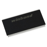
W9412G6IH-5 Winbond Electronics, W9412G6IH-5 Datasheet - Page 2

W9412G6IH-5
Manufacturer Part Number
W9412G6IH-5
Description
IC DDR-400 SDRAM 128MB 66TSSOPII
Manufacturer
Winbond Electronics
Datasheet
1.W9412G6IH-5.pdf
(53 pages)
Specifications of W9412G6IH-5
Format - Memory
RAM
Memory Type
DDR SDRAM
Memory Size
128M (8Mx16)
Speed
250MHz
Interface
Parallel
Voltage - Supply
2.3 V ~ 2.7 V
Operating Temperature
0°C ~ 70°C
Package / Case
66-TSOPII
Lead Free Status / RoHS Status
Lead free / RoHS Compliant
Available stocks
Company
Part Number
Manufacturer
Quantity
Price
Part Number:
W9412G6IH-5
Manufacturer:
WINBOND/华邦
Quantity:
20 000
8.
9.
10.
11.
OPERATION MODE ................................................................................................................. 17
8.1
8.2
8.3
8.4
ELECTRICAL CHARACTERISTICS......................................................................................... 23
9.1
9.2
9.3
9.4
9.5
9.6
9.7
SYSTEM CHARACTERISTICS FOR DDR SDRAM................................................................. 30
10.1
10.2
10.3
10.4
10.5
10.6
10.7
10.8
10.9
TIMING WAVEFORMS ............................................................................................................. 35
11.1
11.2
11.3
11.4
11.5
11.6
7.10.1
7.10.2
7.10.3
7.10.4
7.10.5
7.10.6
7.10.7
Simplified Truth Table................................................................................................... 17
Function Truth Table..................................................................................................... 18
Function Truth Table for CKE ....................................................................................... 21
Simplified Stated Diagram ............................................................................................ 22
Absolute Maximum Ratings .......................................................................................... 23
Recommended DC Operating Conditions .................................................................... 23
Capacitance .................................................................................................................. 24
Leakage and Output Buffer Characteristics.................................................................. 24
DC Characteristics ........................................................................................................ 25
AC Characteristics and Operating Condition................................................................ 26
AC Test Conditions....................................................................................................... 27
Table 1: Input Slew Rate for DQ, DQS, and DM .......................................................... 30
Table 2: Input Setup & Hold Time Derating for Slew Rate ........................................... 30
Table 3: Input/Output Setup & Hold Time Derating for Slew Rate ............................... 30
Table 4: Input/Output Setup & Hold Derating for Rise/Fall Delta Slew Rate................ 30
Table 5: Output Slew Rate Characteristics (X16 Devices only) ................................... 30
Table 6: Output Slew Rate Matching Ratio Characteristics ......................................... 31
Table 7: AC Overshoot/Undershoot Specification for Address and Control Pins......... 31
Table 8: Overshoot/Undershoot Specification for Data, Strobe, and Mask Pins.......... 32
System Notes:............................................................................................................... 33
Command Input Timing ................................................................................................ 35
Timing of the CLK Signals ............................................................................................ 35
Read Timing (Burst Length = 4) ................................................................................... 36
Write Timing (Burst Length = 4).................................................................................... 37
DM, DATA MASK (W9412G6IH) .................................................................................. 38
Mode Register Set (MRS) Timing................................................................................. 39
Burst Length field (A2 to A0)...................................................................... 14
Addressing Mode Select (A3) .................................................................... 15
CAS Latency field (A6 to A4) ..................................................................... 16
DLL Reset bit (A8) ..................................................................................... 16
Mode Register/Extended Mode register change bits (BA0, BA1).............. 16
Extended Mode Register field.................................................................... 16
Reserved field ............................................................................................ 16
- 2 -
Publication Release Date: Sep. 16, 2009
W9412G6IH
Revision A06


