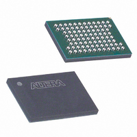
EPC16UC88 Altera, EPC16UC88 Datasheet - Page 11

EPC16UC88
Manufacturer Part Number
EPC16UC88
Description
IC CONFIG DEVICE 16MBIT 88-UBGA
Manufacturer
Altera
Series
EPCr
Datasheet
1.EPC8QC100.pdf
(34 pages)
Specifications of EPC16UC88
Programmable Type
In System Programmable
Memory Size
16Mb
Voltage - Supply
3 V ~ 3.6 V
Operating Temperature
0°C ~ 70°C
Package / Case
88-UBGA
Lead Free Status / RoHS Status
Contains lead / RoHS non-compliant
Other names
544-1228
Available stocks
Company
Part Number
Manufacturer
Quantity
Price
Company:
Part Number:
EPC16UC88
Manufacturer:
ALTERA
Quantity:
62
Company:
Part Number:
EPC16UC88
Manufacturer:
ALTERA
Quantity:
275
Part Number:
EPC16UC88
Manufacturer:
ALTERA/阿尔特拉
Quantity:
20 000
Company:
Part Number:
EPC16UC888N
Manufacturer:
ALTERA
Quantity:
621
Company:
Part Number:
EPC16UC88AA
Manufacturer:
ALTERA
Quantity:
280
Part Number:
EPC16UC88AA
Manufacturer:
ALTERA
Quantity:
20 000
Part Number:
EPC16UC88N
Manufacturer:
ALTERA/阿尔特拉
Quantity:
20 000
Chapter 1: Enhanced Configuration Devices (EPC4, EPC8, and EPC16) Data Sheet
Functional Description
© December 2009 Altera Corporation
f
f
f
For configuration schematics and more information about multi-device FPP
configuration, refer to the appropriate FPGA family chapter in the
Handbook.
Passive Serial Configuration
APEX 20KC, APEX 20KE, APEX 20K, APEX II, Cyclone series, FLEX 10K, and Stratix
series devices can be configured using enhanced configuration devices in the PS
mode. This mode is similar to the FPP mode, with the exception that only one bit of
data (DATA[0]) is transmitted to the FPGA per DCLK cycle. The remaining
DATA[7..1] output pins are unused in this mode and drive low.
The configuration schematic for PS configuration of a single FPGA or single serial
chain is identical to the FPP schematic (with the exception that only DATA[0] output
from the enhanced configuration device connects to the FPGA DATA0 input pin;
remaining DATA[7..1] pins are left floating).
For configuration schematics and more information about multi-device PS
configuration, refer to the appropriate FPGA family chapter in the
Handbook.
Concurrent Configuration
Enhanced configuration devices support concurrent configuration of multiple FPGAs
(or FPGA chains) in PS mode. Concurrent configuration is when the enhanced
configuration device simultaneously outputs n bits of configuration data on the
DATA[n-1..0] pins (n = 1, 2, 4, or 8), and each DATA[] line serially configures a
different FPGA (chain). The number of concurrent serial chains is user-defined via the
Quartus II software and can be any number from 1 to 8. For example, three concurrent
chains you can select the 4-bit PS mode, and connect the least significant DATA bits to
the FPGAs or FPGA chains. Leave the most significant DATA bit (DATA[3])
unconnected. Similarly, for 5-, 6-, or 7-bit concurrent chains you can select the 8-bit PS
mode.
Figure 1–3
PS mode using an enhanced configuration device.
For specific details about configuration interface connections including pull-up
resistor values, supply voltages, and MSEL pin settings, refer to the appropriate FPGA
family chapter in the
shows the schematic for configuring multiple FPGAs concurrently in the
Configuration
Handbook.
Configuration Handbook (Complete Two-Volume Set)
Configuration
Configuration
1–11


