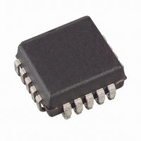
AT17C002A-10JI Atmel, AT17C002A-10JI Datasheet - Page 5

AT17C002A-10JI
Manufacturer Part Number
AT17C002A-10JI
Description
IC SRL CONFIG EEPROM 2M 20PLCC
Manufacturer
Atmel
Datasheet
1.AT17C002A-10JC.pdf
(14 pages)
Specifications of AT17C002A-10JI
Programmable Type
Serial EEPROM
Memory Size
2Mb
Voltage - Supply
4.5 V ~ 5.5 V
Operating Temperature
-40°C ~ 85°C
Package / Case
20-LCC (J-Lead)
Lead Free Status / RoHS Status
Contains lead / RoHS non-compliant
AT17A Series
Reset Polarity
Programming
Mode
Standby Mode
2280B–08/01
The READY pin is available as an open-collector indicator of the device’s reset status; it is
driven Low while the device is in its power-on reset cycle and released (tri-stated) when the
cycle is complete. It can be used to hold the FPGA device in reset while it is completing its
power-on reset but it cannot be used to effectively delay configuration (i.e., the output is
released well before the system V
The first AT17A Series device clocks all subsequent AT17A Series devices until configuration
is complete. Once all configuration data is transferred and nCS on the first AT17A Series
device is driven High by CONF_DONE on the FPGA devices, the first AT17A Series device
clocks 16 additional cycles to initialize the FPGA device before going into zero-power (idle)
state. If nCS on the first AT17A Series device is driven High before all configuration data is
transferred – or if the nCS is not driven High after all configuration data is transferred – nSTA-
TUS is driven Low, indicating a configuration error.
The AT17A Series Configurator allows the user to program the polarity of the OE pin as either
RESET/OE or RESET/OE. For more details, please reference the “Programming Specification
for Atmel’s FPGA Configuration EEPROMs” application note.
The programming mode is entered by bringing SER_EN Low. In this mode the chip can be
programmed by the 2-wire serial interface. The programming is done at V
gramming supervoltages are generated inside the chip. See the “Programming Specification
for Atmel’s Configuration EEPROMs” application note for further information. The AT17 A-
series parts are read/write at 5V nominal. The AT17LV A-series parts are read/write at 3.3V
nominal.
The AT17A Series Configurator enters a low-power standby mode whenever nCS is asserted
High. In this mode, the configuration consumes less than 0.5 mA of current at 5V. The output
remains in a high-impedance state regardless of the state of the OE input.
CC
has stabilized).
CC
supply only. Pro-
5


