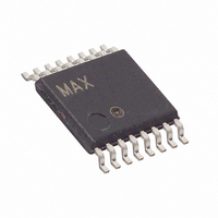
DS2764AE+ Maxim Integrated Products, DS2764AE+ Datasheet

DS2764AE+
Specifications of DS2764AE+
Related parts for DS2764AE+
DS2764AE+ Summary of contents
Page 1
GENERAL DESCRIPTION The DS2764 high-precision Li+ battery monitor is a data-acquisition, information-storage, and safety- protection device tailored for cost-sensitive battery pack applications. This low-power device integrates precise temperature, voltage, measurement, nonvolatile (NV) data storage, and Li+ protection into the ...
Page 2
ABSOLUTE MAXIMUM RATINGS Voltage Range on PLS and CC Pins, Relative to V Voltage Range on Any Other Pin, Relative to V Continuous Internal Sense Resistor Current Pulsed Internal Sense Resistor Current Operating Temperature Range Storage Temperature Range Soldering Temperature ...
Page 3
ELECTRICAL CHARACTERISTICS: PROTECTION CIRCUITRY (2.5V V 5.5V 0°C to +50°C PARAMETER Overvoltage Detect Charge Enable Undervoltage Detect Overcurrent Detect Overcurrent Detect Short-Circuit Detect Short-Circuit Detect Overvoltage Delay Undervoltage Delay Overcurrent Delay Short-Circuit Delay Test ...
Page 4
ELECTRICAL CHARACTERISTICS: 2-WIRE INTERFACE (2.5V V 5.5V -20C to +70C PARAMETER SCL Clock Frequency Bus Free Time Between a STOP and START Condition Hold Time (Repeated) START Condition Low Period of SCL Clock High ...
Page 5
The maximum t has only to be met if the device does not stretch the LOW period (t Note 14: HD:DAT This device internally provides a hold time of at least 300 ns for the SDA signal (referred to the ...
Page 6
PIN DESCRIPTION PIN SYMBOL FLIP TSSOP CHIP PLS SNS IS2 9 D4 IS1 10 E4 SDA 11, 12 ...
Page 7
Figure 2. Block Diagram SDA 2-Wire INTERFACE SCL THERMAL SENSE V MUX IN + IS1 - IS2 PLS PS SNS IS2 DETAILED DESCRIPTION The DS2764 high-precision Li+ battery monitor is a data-acquisition, information-storage, and safety-protection device tailored for cost-sensitive battery ...
Page 8
Figure 3. Application Example 102 x 2 PACK+ 1k 150 4.7k PS 102 PACK- NOTE PRESENT FOR EXTERNAL SENSE RESISTOR SNS CONFIGURATIONS ONLY. NOTE PRESENT FOR INTERNAL SENSE RESISTOR SNS-INT CONFIGURATIONS ONLY. 1k 1k ...
Page 9
POWER MODES The DS2764 has two power modes: active and sleep. While in active mode, the DS2764 continually measures current, voltage, and temperature to provide data to the host system and to support current accumulation and Li+ safety monitoring. In ...
Page 10
Overcurrent, Charge Direction. The voltage difference between the IS1 pin and the IS2 pin (V filtered voltage drop across the current-sense resistor than overcurrent delay t , the DS2764 shuts off both external FETs and sets the COC ...
Page 11
CURRENT MEASUREMENT In active mode, the DS2764 continually measures the current flow into and out of the battery by measuring the voltage drop across a current-sense resistor. The DS2764 is available in two configurations: 1) internal 25m current-sense resistor and ...
Page 12
CURRENT OFFSET COMPENSATION The current measurement and current accumulation are internally compensated for offset on a continual basis minimizing error resulting from variations in device temperature and voltage. Additionally, the Current Offset Bias register is a user programmable constant bias ...
Page 13
POWER SWITCH INPUT The DS2764 provides a power control function that uses the discharge protection FET to gate battery power to the system. The PS pin, internally pulled the DS2764 is in sleep mode, the detection ...
Page 14
Table 2. Memory Map ADDRESS (HEX) 00 Protection Register 01 Status Register 02–06 Reserved 07 EEPROM Register 08 Special Feature Register 09–0B Reserved 0C Voltage Register MSB 0D Voltage Register LSB 0E Current Register MSB 0F Current Register LSB 10 ...
Page 15
CC—CC Pin Mirror. This read-only bit mirrors the state of the CC output pin. DC—DC Pin Mirror. This read-only bit mirrors the state of the DC output pin. CE—Charge Enable. Writing this bit disables charging (CC output ...
Page 16
BL2—EEPROM Block 2 Lock Flag this read-only bit indicates that EEPROM block 2 (addresses 40 to 47) is locked (read-only) while a 0 indicates block 2 is unlocked (read/write). The special order unique 64-bit ID device does ...
Page 17
BUS SYSTEM The 2-Wire bus system supports operation as a slave only device in a single or multi-slave, and single or multi- master system 128 slave devices may share the bus by uniquely setting the 7-bit slave ...
Page 18
Bus Timing The DS2764 is compatible with any bus timing up to 100kHz. No special configuration is required to operate at any speed. 2-Wire Command Protocols The command protocols involve several transaction formats. The simplest format consists of the master ...
Page 19
Read Data Protocol The Read Data protocol is used to read register and shadow RAM data from the DS2764 starting at memory address specified by MAddr. Data0 represents the data byte in memory location MAddr, Data1 represents the data from ...
Page 20
... © 2006 Maxim Integrated Products 48-BIT SERIAL NUMBER PACKAGE INFORMATION TSSOP, External Sense Resistor, 4.275V V TSSOP, External Sense Resistor, 4.35V V DS2764AE+ on Tape-and-Reel DS2764BE+ on Tape-and-Reel TSSOP, 25m Sense Resistor, 4.275V V TSSOP, 25m Sense Resistor, 4.35V V DS2764AE+025 in Tape-and-Reel DS2764BE+025 in Tape-and-Reel Flip-Chip, 25m Sense Resistor, Tape-and-Reel, 4.275V V Flip-Chip, 25m ...


